


Janky Tape Echo
Build Guide
Introduction
Build your own tape echo!
Looking to create unique and interesting ambience sounds for your music? Look no further than the Janky, a real tape echo effect pedal that's can be built at home.
Using a cheap portable cassette player, 3D printing and easy-to-find parts, the Janky creates a cassette-vibe, lo-fi, warbley, noisey, glitchy echo effect for use with guitars, vocals, synthesisers, and more.
Best of all, the Janky is entirely open-source.
To get started, download the project files here. These files include the Bill Of Materials, which lists everything you need, both parts and tools. There are also links to a supplier for most of the parts we use.
Please read through all instructions before you get started - this isn't your average DIY pedal build and there are many opportunities to make mistakes.
Want to support our band? Check out our music and consider giving it a share. Thanks for checking out the Janky and happy building!
Godspeed!


Take A Listen
Stuff We Sell
We sell a number of items on our merch store which can make your build easier. You don't need to buy anything from us to make a Janky Tape Echo - everything is open source - but if you do grab parts from us it will help in supporting the bands musical endeavours and developing more weird, open source pedal ideas.
Kits and Components
Band Merch
We also sell band related stuff, like T-shirts. It would really help us out if you grab some merch.
Stuff We Don't Sell
Assembled Machines
We don't sell ready assembled machines. Please don't contact us asking us to sell you one. We very occasionally offer machines to friends and musicians we respect, but not to the general public. In order to keep it working, the Janky requires more maintenance than commercially available pedals and so selling assembled machines is not appropriate.
Discord
You can chat about your build with other Janky enthusiasts on our public discord server.
Project Download
The latest version of the project files are available to download here.
You can also get the files via our GitHub project page.
Contents
1.0 Before You Get Started
1.1 Safety
1.2 Support
1.3 Versions
1.4 Power Supply
1.5 Switching
1.6 Cassette Heads
1.6.1 Sourcing Heads
1.6.2 Read and Write Heads
1.6.3 Erase Heads
1.6.4 Four Track Heads
1.6.5 Other Kinds Of Heads
1.7 Tape Loops
1.8 Reels
1.9 Contact Pads
1.10 Tools
1.11 PCB Headers
1.12 Hardware
1.13 Wiring
2.0 How The Machine Works
3.0 The Enclosure
3.1 3D Printing
3.1.1 Getting To Know The Enclosure
3.1.2 Filaments
3.1.3 Slicer Settings
3.2 Post Processing
3.2.1 Heat Set Inserts
3.2.2 EM Shielding
4.0 The Cassette Player
4.1 Sourcing The Machine
4.2 Expose The Electronics
4.3 Hacking the Tape Player
4.3.1 Disconnect The Battery Compartment
4.3.2 Disable Auto-Reverse
4.3.3 Desolder The Wiring
4.3.4 Solder In The New Wiring
4.3.5 Exposing the Head Input
4.3.6 Secure the PCB
4.3.7 Replace The Head Wiring
4.3.8 The Motor Wires and Groundings
4.3.9 Crimp the Motor and Tape Power Wires
4.3.10 Enclosure grounding
4.3.11 Remove The Second Pinch Roller
4.3.12 Remove The Eject Button Plastic
4.3.13 Final Touches
5.0 Electronics
5.1 Main Board Prep
5.1.1 The Jacks
5.1.2 The ground link
5.1.3 The JST XH Headers
5.1.4 The IDC Box Header
5.2 Power Supplies
5.2.1 12V Main Supply
5.2.2 9V Bias Oscillator Supply
5.2.3 6V Motor Supply
5.2.4 3V3 Tape Player Supply
5.2.5 Buffered Virtual Ground
5.2.6 Test All Voltages
5.3 Digital Circuitry
5.3.1 The Arduino Nano
5.3.2 Arduino Power Up Test
5.3.3 The True-Bypass Switching
5.3.4 The Motor Controller
5.3.5 The Remote Jack
5.3.6 Test the switching and 9V Bias Power Supply
5.4 Main PCB Audio Circuitry
5.4.1 Main Board Input Stage
5.4.2 Main Board Output Stage
5.5 The Control Board
5.5.1 Control Board IDC Box Header
5.5.2 Control Board JST XH Headers
5.5.3 Control Board Bias Trap
5.5.4 Input Filtering and Feedback Mix
5.5.5 Control Board Output Stage
5.5.6 Front Panel Potentiometers
5.5.7 Head Select Switch
5.6 Audio Stage Testing
5.6.1 Make The Test Jack
5.6.2 Test The Input Audio Stage
5.6.3 Test The Output Audio Stage
5.7 The Bias Oscillator
6.0 Assembly
6.1 Install The Tape Guides
6.1.1 Cutting Steel Rod
6.1.2 Install Bearings
6.1.3 Install The Tape Guides
6.2 Mounting The Tape Player
6.3 Initial Assembly Of The Enclosure
6.4 Adding The Viewing Window
6.5 Installing The Main PCB
6.6 Connect Up The Wiring
6.6.1 Tape Power, Motor and Long Read Head Wiring
6.6.2 Ribbon Cable
6.6.3 Remote Jack
6.6.4 Playback Connector
6.7 Heatsink
6.8 Installing The First Tape Loop
6.9 Fit The Front Panel Knobs
7.0 Installing Heads
7.1 The Record Head
7.1.1 Soldering On The Wiring
7.1.2 Add The JST XH Connector
7.1.3 Mount The Head
7.2 The Short Read Head
7.2.1 Soldering On The Wiring
7.2.2 Add The JST XH Connector
7.2.3 Mount The Head
7.3 The Erase Head
7.3.1 Soldering On The Wiring
7.3.2 Add The JST XH Connector
7.3.3 Mount The Erase Head
7.4 The Long Read Head
7.5 Connect The Wiring
8.0 Testing
8.1 Motor Test
8.2 Bias Oscillator Test
8.3 Audio Test
9.0 Final Steps
Appendix 1.0 Debugging
Appendix 2.0 Head Alignment
Appendix 3.0 Tuning Your Janky
Appendix 4.0 Making Your Janky Robust
Appendix 5.0 Making Head Adapters
A5.1 Taking Measurements
A5.2 CAD Work
Appendix 6.0 Making XH Connectors
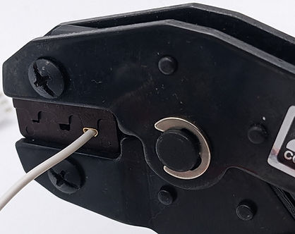
A6.1 How To Crimp a JST XH Header
Appendix 7.0 Legal Mumbo-Jumbo
Credits
1.0 Before You Get Started
Please read the following information carefully. It's important stuff.
1.1 Safety
Always use appropriate safety gear when working with electronics and soldering tools. Wear safety goggles. Solder can spit and cause blindness. Capacitors wired in backwards by mistake can explode. Capacitors that are rated incorrectly can explode. Capacitors can also just explode because they feel like it. Don’t trust capacitors. Always wear goggles when soldering or powering up any circuit for testing.
1.2 Support
There is no support: This is an open source, DIY project. It should go without saying that everything provided here is without guarantee or warranty. We provide no one-to-one support. We sell parts and kits to make this easier (and cheaper) for you, and also so that we can get some much needed cash for our band. But, we can’t offer direct help with your build - we just don’t have the time to support everyone and these builds are complex. If you suspect something we’ve sold you is faulty, then of course get in touch. But, we won’t help you debug your rats nest of wiring or bad soldering job.
1.3 Versions
Please ensure that all materials (PCBs, 3D printer files, schematics, bill of materials etc.) are for the same version. The version number is printed on the PCBs and all associated digital materials are under a release with that same version number.
1.4 Power Supply
This unit requires a 12V 1A DC Center Negative power supply. Ensure you use a good quality supply to reduce noise and ensure healthy operation.
1.5 Switching
The main enclosure does not include a space for a footswitch. Instead, we include a Remote jack. This is a space for a ¼” mono jack which can be used to connect a remote footswitch. This can be any standard momentary "push-to-make" footswitch that connects via ¼” lead. These are available from many suppliers online.
1.6 Cassette Heads
The Janky uses as many as four cassette heads, three read/write heads and one active erase head. One read head is provided by the donor tape player that we use in the construction of the Janky, meaning that you need to source the extra two read/write heads and one active erase head.
1.6.1 Sourcing Heads
Heads can be sourced in a range of ways. Firstly, heads are available from online suppliers at very low prices - usually on the order of a couple of quid per head. We've had good luck sourcing from AliExpress and eBay.
Secondly, heads can be found by salvaging them from other tape machines or cassette equipment. This requires a little more skill, as you need to disassemble and de-solder the head from the machine, but is a perfectly acceptable way to get hold of the heads you need. We would not recommend taking apart a perfectly good, working tape machine for this purpose while heads are still freely available online at low cost - but there are many places, such as charity shops and boot sales, where you can source old or broken machines that can donate their heads to a worthy cause. Remember that you can also find cassette heads in places other tape machines - one such example being car CD adapter cassettes.
Heads used for reading and writing 1/8" cassette tape are generally interchangeable. The only main differences to be aware of are:
-
Physical dimensions. Tape heads are not standardised in their dimensions or mounting hole positions. In order to fit the heads into the Janky, you will need to make some head adapters. We may offer some pre-made head adapter designs in the project package (look under STL/Premade Head Adapters), but these would rely on you sourcing the exact model of head that the adapter is designed for. If you look on AliExpress or eBay you can usually find heads by their model number. If you need to make your own adapters, we will tackle this in Appendix 5.0. It is advisable to use the same model of head for both the read and write heads. This way, you only need to make up one adapter design.
-
Mono, stereo and four-track heads. All of these heads will work perfectly well with the Janky. However to get the most out of four-track heads, some changes to the way the heads and tape player are wired will be needed. See the Four Track section further down for more info. We recommend using stereo heads.
-
Coil inductance and resistance. Different heads have different specifications for coil inductance and resistance, which will influence the tone of the machine to some degree.
Before using any cassette heads in the Janky, it can be a good idea to use some isopropyl alcohol on a soft rag to rub down the front surfaces of your heads to ensure they're clean.
Most heads you can find for sale online are either new-old-stock, meaning they've either been sat in storage for years, or they've been salvaged from old, dead equipment. Heads taken from old equipment may have some sticky residue coating them, as the glue that binds the coating on some cassette tapes degrades over time and causes a residue build-up. Any residue or dirt that has accumulated on the head over the years can cause our tape to stick to the heads and jam, and we don't want that. If you're finding your tape sticks and jams at the heads regularly, this may well be your problem.
1.6.2 Read and Write Heads
Cassette heads can be used for both reading from tape, and writing to tape. Generally, we like to try and use the same model of head for both the read and write heads in the Janky - this makes fitting the heads into the machine much easier. However, you can use different heads for the read and write functions if you wish.

A selection of different cassette heads
As you can see from the above photo, the different models of heads all have different dimensions and mounting hole positions. However, the anatomy of the heads is all roughly the same.

Anatomy of a cassette head
Besides the obvious differences in size, the main distinction between different heads is in the number of pickups (and thus the number of pins on the back of the head for wiring) and the inclusion of a guide fork.
-
The pickups will be different depending on whether it's a mono, stereo or four-track head. Mono heads will have 2 pins for wiring, stereo will have 4 pins and four-track will have 8 pins.
-
Not all heads will include a guide fork. We recommend that you choose heads that do, simply because it makes the process of mounting and aligning the heads easier. However, heads without forks will work, too.
1.6.3 Erase Heads
Erase heads come in two basic kinds, active and passive. You will need an active erase head. Passive heads consist only of a static magnet and will not work in the Janky. This is because the erase head is an integral part of how the electronics in the Janky work, so you must find an active erase head.

An active erase head
1.6.4 Four Track Heads
Four track heads are heads the can read or write to all four channels of the cassette tape at the same time. These will have four pickups and eight wiring pins.
These heads will work with the Janky. You can either simply only connect up half of the head (4 out of the 8 pins), or for improved fidelity you can connect all pins.
Using all four tracks yields better performance because you're essentially using physically wider tape and therefore have more physical space upon which to store your audio signal. This has the effect of increasing the available dynamic range.
Note that in order to get any fidelity improvement, all heads will need to be four track heads. This includes the erase head!
Luckily, the read head included in the tape player is a four track head. The tape player is designed to support playback in either direction; a feature called auto-reverse. However, the head isn't wired for four-track operation. So in order to use four track heads at full tape width, some extra hacking of the cassette player is needed in order to wire all the pickups of the head together. We don't cover that in this guide, but it shouldn't be hard to figure out if you want to try that. If you're unsure, then we'd recommend starting small and building using ordinary mono/stereo heads, first!
1.6.5 Other Kinds Of Heads
There are various other kinds of tape heads available. These can include:
-
Combined erase and record heads that can both erase the tape and write to it all in a single head. In theory, these can be used in the Janky. You could replace the erase head with a combined erase and record head, and then you would have the record head position in the Janky free for a third read head. This would offer more options of tape speed vs. delay time. There would need to be changes made to the head routing electronics and wiring to support all three positions, or the original tape machines read head would need to be left disconnected.
-
1/4" and 1/2" tape heads. These are designed for much wider tape than the 1/8" tape that cassette machines use, and is therefore not compatible with the Janky. Typically 1/4" and 1/2" heads are used in high quality studio tape machines, where the extra tape width provides much better dynamic range.
-
Bias heads. These are rare, but heads specifically designed for feeding the bias signal from the opposite side of the tape to the record head do exist
We generally recommend avoiding these kinds of heads unless you want to make some serious modifications to the electronics and CAD files to support them.
1.7 Tape Loops
The Janky makes use of short loops of cassette tape, which you will need to make yourself. We make these by salvaging tape from inside of a cassette. If you have ever created a looping cassette, the process is similar. If not, don't worry, we take you through the process of making a loop in Section 6.8.
Whilst any cassette tape will work, not all cassettes are born equal. Your typical C-90 audio cassette contains thin, stretchy, low quality tape. As mentioned, this will work in the Janky, but it will be prone to snagging, tape jams and the loop shredding into tiny pieces. It can still be useful to make loops from this kind of tape. One reason is that this tape is very cheap and easy to come by - our bass player once turned up to practice with carrier bags full of cassettes that he bought at a boot sale for £1 a bag - and so because of this, it makes good throw-away tape for practicing making loops or performing tests on your Janky.

Some standard C-90 audio cassettes
Another reason is that this tape sounds different to the other, higher quality tape we're going to discuss. Not only because the magnetic coating has a different composition, but also because you will get more snagging and tape damage occurring, which will have audible artefacts. Indeed, you can purposefully scrunch up and damage the tape loop before installing it into the Janky as a means to get more textural noise for musical purposes if that's your thing.
However, for day-to-day operation - especially when using the Janky in a live setting - you will probably want to be using something more reliable. Now, no tape is ever going to be 100% reliable. You can make the machine more reliable by installing better quality, better made loops and ensuring minimal friction in the tape path and the correct tension between the loop and the heads, but any loop can and will fail at any time. Think of loops like guitar strings - sometimes they last a month, sometimes you break the string right after putting it on the guitar. Sometimes it'll happen right in the middle of a show.
But, if you want the most reliable loops, then you need to be using tape from computer cassettes, such as C-10 and C-15 computer cassettes.

A new-old-stock C-10 computer cassette. The holy grail of looping reliability.
This tape is noticeably much, much thicker than the kind found in audio cassettes, and is completely compatible with audio cassette heads. Unlike audio cassettes, where a single piece of tape is intended to be played once or twice a day as the user listens to their favourite jam, computer cassettes are designed to run back and forth over the same parts of the tape - reading and re-reading the same data many times. It is for this reason that the tape is thicker. The magnetic coating on this kind of tape is also formulated to be more wear resistant, both to the physical stress of running over the face of the heads, but also to the magnetic stress of being written and erased continually.
The downside? They're becoming rare, and with that, expensive. Expect to have to pay £10 or even £15 for a single cassette.
1.8 Reels
The Janky requires two open reels. Besides looking awesome, these serve as tape guides that keep the tape loop in place while it runs around the machine.
The easiest way to get hold of a set of reels is to buy some custom ones from our merch store, assuming that we have some in stock.

Some Indifferent Engine brand reels.
However, they can also be taken out of reel to reel cassettes. Simply source any reel-to-reel C-cassette, open it up and strip the magnetic tape away, leaving you with a couple of empty reels.
1.9 Contact Pads
The Janky requires three felt contact pads. These are small pieces of felt material stuck to a piece of sprung metal. They can be harvested from audio cassettes.

Felt contact pads, stolen from out three audio cassettes
1.10 Tools
To complete this project, there are a few tools you will need. Here is a short list out. For an exhaustive list of everything you need - tools, components, hardware - please refer to the 'All Parts' sheet in the Bill Of Materials spreadsheet file included in the project download package.
Tools you will need:
-
3D printer
-
Soldering iron
-
Heat set insert tool in M2, M3 and M4 sizes (optional, but recommended)
-
Desoldering pump (optional, but recommended)
-
Wire snips
-
Wire strippers
-
Hot glue gun
-
Anti-static tweezers
-
A small flat-head screwdriver
-
A small phillips head screwdriver
-
JST XH crimping tool (optional, but recommended)
-
Crimping tool for M3 sized terminal washers (optional, but recommended)
-
Some strong pliers with a sharp cutting edge (optional, but recommended)
-
Heat gun (or lighter, heat gun is much prefered)
-
A set of calipers (optional, but recommended)
-
A PC or Mac with a USB connection
-
Allen keys for M2, M3 and M4 size hex cap bolts
-
Digital multimeter
-
Pocket scope (optional, but may be needed for debugging).
-
Crimping tool for M3 size ring terminals (optional, but recommended)
-
Spanners in 8mm, 10mm, 11mm and 13mm sizes.
-
An electric screwdriver with M4 hex key is useful (optional)
1.11 PCB Headers
We recommend using JST XH headers throughout your build. We have found these to be the most reliable way to handle various aspects of off-board wiring and they result in a clean, professional finish.

JST XH connectors and headers make for a clean look to the off-board wiring.
However, this would require that you own a JST XH crimping tool. Unofficial ones can be had for reasonable money, and if you intend on building a lot of DIY electronics it's a useful tool to have. For instructions on how to make JST XH connectors, take a look at Appendix 6.0.
Having said that, you can choose to go without this tool. You can instead use screw terminals in place of the JST XH headers on the PCB.

A 3-way, 2.54mm pitch screw terminal block
Screw terminals with a 2.54mm lead pitch (this is the distance apart the pins are) will fit. You will need three 2-way terminals and six 3-way terminals. Simply replace all 2 pin and 3 pin headers on the main and control PCBs with screw terminals of the same pin count. Tin your wires and screw them into the terminals.
The downside to using screw terminals is that, in our experience, the connections are not as robust. Wires can work themselves loose from the terminals or break off under strain. To mitigate this, you can choose to hot glue the wires into the terminals once your Janky is finished and tested. This works great because it makes the connection much more robust but can still be removed for servicing. When you want to remove the wire, simply use snips or a craft knife to cut away the glue. Just be sure not to use too much glue - use just a small dab to secure the wire to the terminal block.
Whatever you do, don't solder your offboard wiring directly the PCBs. In the event the machine doesn't work as expected, this will make debugging impossible. Further, at some point you will need to disassemble the machine, at least partially, to perform maintenance. You will need to replace tape loops when they break or wear out. You will need to occasionally clean and lubricate the mechanical parts of the tape transport. You will eventually need to replace the rubber belt (we provide an STL for a replacement belt you can print in flex filament on your 3D printer). All of these things require unhooking at least some wiring from the PCBs and if you've soldered in your wiring you won't be able to do that.
1.12 Hardware
The enclosure includes a number of pieces of vitamins (off-the-shelf hardware components). Please consult the Bill Of Materials file for an exhaustive list and links to possible suppliers, but here is a short list of things you will need.
-
Five lengths of 2mm diameter steel rod, cut to lengths of 12mm. Either order a long length and cut with strong pliers, or order pre-cut to length.
-
Ten 2mm x 5mm x 2mm bearings.
-
Stereo angled 3.5mm audio cable. Must be at least 10cm long.
-
An acrylic window - there are many suppliers world-wide that can supply these. See Section 6.4 for details.
- You may need a as many as three cassette felt contact pads. You can find these inside of most cassettes.
-
Various lengths of M2, M3 and M4 bolt. See the Bill of Materials for an accurate list.
-
M2 and M3 washers for bolts.
-
Six 8mm M3 grub screws for attaching knobs to potentiometers.
-
Brass heat-set inserts in M2, M3 and M4 sizes.
-
A 26-way IDC ribbon cable, 15cm to 20cm in length.
-
An M3 size ring terminal.
-
A couple of 1/4" mono open jacks. We need one for the actual build, but it's useful to have a second one to hand for testing purposes.
1.13 Wiring
In this project, there is a lot of off-board wiring, but it mostly falls into four types:
-
Stranded hook-up wire. All of this kind of wiring will be crimped for JST headers, so it can be a good idea to test-crimp some scrap wire before you start to make sure that the crimps hold well. You'll need colours of red, black and white. We tend to find thicker gauges crimp better, so we recommend 22 gauge.
-
Shielded 2 core grey audio cable. This should have 2 conductors (red, white) and an overall shield.
-
A single 26-way IDC ribbon cable, which is used to connect the main electronics board to the control electronics board.
-
Some female Dupont wires, these are optional, but very useful for testing.
2.0 How The Machine Works
The Janky is a tape echo - an echo effect which uses real cassette tape to introduce a time delay for atmospheric, musical awesomeness.
The audio signal is written to the tape and read back from the tape by a series of cassette heads. As it passes over a write head, data is written to the tape. Then, that data is read back as it passes over a read head. Because the write head and read head are separated by some distance along the tape, it takes time for the data written at the write head to reach the read head - hence the time delay.
Unlike in a standard cassette tape, the tape is arranged in a closed loop that travels around and around, continually passing over the write head and read head over and over again. Because of this, an erase head is also included, just before the write head, that cleans away the previous data that was written to the tape.
The amount of delay can be adjusted by adjusting the speed at which the tape runs. If the tape runs slowly, it takes longer for the data written at the write head to reach the read head and a longer delay time is created. Likewise, if the tape runs fast, it takes less time.
The pedal is built from a combination of a hacked walkman-style cassette player, 3D printed parts and some custom electronics. The cassette player provides the mechanical parts that we need to handle driving the tape - a motor with the necessary belt, pulleys and gears, as well as a pinch roller to grip and move the tape. The 3D printed parts allow us to add the extra heads that we need to enable erasing and writing to the tape, and to fashion an enclosure to house everything. Finally, the custom electronics allow us to regulate the motor speed, write data to the tape and handle mixing the tape signal into the unprocessed signal.
In this guide, we will go through each of these areas in turn. We will 3D print and assemble the various enclosure parts that we need, prepare our cassette player and make our custom electronics.
3.0 The Enclosure
This section deals with preparing the enclosure for our tape echo.
3.1 3D Printing
Printing the parts for these machines is straight forward for anyone with a little printing experience. Any desktop FDM printer with a build volume bigger than 160mm x 150mm x 50mm will do fine.
We have printed using a Prusa Mini+, an Ender 3 v2 and an Ender 3 S1 Pro. All three of these machines provided perfectly useable parts, but in our experience the Mini+ provided the best quality.
All 3D printer files are located under the STL directory in the project files.
To begin with, print all parts. You will need:
-
Enclosure Body.stl
-
Enclosure Lid.stl
-
Enclosure Bottom Plate.stl
-
Transport Mount.stl
-
Head Mount.stl
-
Guide Topper 1.stl
-
Guide Topper 2.stl
-
2 x Reel Clamp.stl
-
6 x Knob.stl
-
3 x Head Adapters
You will also need to print three Head Adapters. Which adapters you print depends on which heads you have. You will need three adapters - two for the read/write heads and one for your erase head.
We supply some pre-made adapters for at least one make of cassette head for both read/write and erase. These are located under the STL/Premade Head Adapters folder. The subfolders are named after the model of cassette head.
You can also design your own head adapters, there are instructions showing you how to do this in Appendix 5.0.
3.1.1 Getting To Know The Enclosure
In this section we will go through and identify each of the 3D printed parts and what it does.
Enclosure Body
This forms the main body of the enclosure into which the main PCB mounts. The PCB is held in place by the two audio jacks and the power jack. There is also an extra mounting hole for an open 1/4" mono jack that will be used for connecting a remote footswitch. The top side of the part features a recessed area into which the Head Mount is slotted.
Print orientation: Print with the underside (the completely flat surface) on the bed.


Enclosure Lid
The lid of the enclosure. The control PCB mounts to the underside of this, held in place by the potentiometers. It also includes the mounting holes for the 3PDT head select switch and the viewing window.
Print orientation: Print face down, so that the text on the lid is on the print bed.
Enclosure Bottom Plate
The final part of the large external enclosure parts, the bottom plate goes beneath the Enclosure Body and accepts four 65mm M4 hex cap bolts to hold the enclosure together.
Print orientation: Print with the 'Jacks This End' text facing the bed.


Transport Mount
The transport mount is designed to mate to the hacked cassette player. It also has spaces for the decorative open cassette reels. There is also a small mounting hole intended to hold a steel rod and bearings which act as a tape guide.
Print orientation: Print with the large, flat surface facing the bed.
Head Mount
The head mount is designed to accommodate the extra tape heads that we need for erasing, writing and reading the tape. It connects to the Transport Mount and press-fits into the Enclosure Body. There are several mounting holes to hold steel rods and bearings, which act as tape guides.
Print orientation: Print with the large, flat surface facing the bed.


Small Guide Topper
The guide topper holds the steel guide and bearings in place on the Transport Mount. This prevents the guide from falling out of the Transport Mount.
Print orientation: Print with side with three holes in facing up away from the bed.
Large Guide Topper
This guide topper holds the steel guides and bearings in place on the Head Mount. This prevents the guides from fall out of the Head Mount.
Print orientation: Print with the large, flat surface facing the bed.


Reel Top Clamp
The reel clamps bolt down onto pillars on the Transport Mount and are positioned over the top of the decorative reels. This prevents the reels from coming loose when the machine is upside-down.
Print orientation: Print with the flat surface facing the bed, with the round, protruding section of the clamp facing up.
Knobs
The machine has six potentiometers for controlling various aspects of the delay effect. There are many off-the-shelf knobs available that will fit the potentiometers that we specify for the design, but to complete the look of your machine we have included a design for a D-shaft knob that you can print in matching filament.
Print orientation: Print with the top of the knob facing the bed, so that the knob prints upside down.


Head Adapters
Head adapters are required in order to mount cassette heads into the Head Mount.
We decided not to specify a single cassette head make/model for the Janky. Cassette heads are no longer manufactured, and so by avoiding relying on a single type of head we can increase the chances that you will be able to source heads for your build.
However, cassette heads are not standardised in their size, shape and mounting hole positions, and so it is necessary to use small adapters that fit your head and marry to the Head Mount.
We supply a small number of designs for some models of head in the project files under the STL/Premade Head Adapters folder.
If you have different heads, then you will need to do some light CAD work to make your head adapters. Don't worry, it's easy and there are step-by-step instructions using the free, browser based CAD software TinkerCad. See Appendix 5.0 for the instructions.
3.1.2 Filaments
PLA filaments work great, as will PETG. Other filaments, such as ABS, will likely provide stronger printed parts. However, they come at an increased difficulty in printing.
In general we recommend using PLA filaments because they provide enough strength for what is needed, they are by far the easiest to print on a desktop FDM printer and they are available in a wide range of attractive colours and finishes. PLA is also the most environmentally friendly - especially if you source recycled filament on cardboard reels. Finally, it does not require printing in an enclosure or any filtering, which filaments such as ABS and ASA require.
In developing the Janky, we have tested a range of filament brands and settled on using PolyTerra Charcoal Blank PLA for the external enclosure parts and a range of different, brightly coloured PLA filaments for the internal machine parts. Whilst the PolyTerra filaments yielded the best quality results in our setup, we did not find any PLA filament that didn't produce usable parts.
3.1.3 Slicer Settings
We recommend a layer height of 0.2mm and infill density of 20% for all parts, except for the head adapters.
Head adapters should be printed at the smallest available layer height for maximum dimensional accuracy in the vertical axis. For example, we print our head adapters using the PrusaSlicer Ultra Detail profile, which uses a 0.05mm layer height.
For a stronger part, you can increase the infill density. However, this will greatly increase print times. In our experience, 20% infill produces parts that are strong enough. The enclosure is secured closed using four 65mm M4 steel bolts which go through the entire height of the enclosure. This adds a significant amount of rigidity and we feel that adding further rigidity by increasing the infill density isn't therefore required.
3.2 Post Processing
Some light post-processing of the 3D printed parts is required after printing.
3.2.1 Heat Set Inserts
In order to be able to bolt the enclosure together, it is necessary to install some brass inserts into the 3D printed parts. These are small, threaded inserts in M3 and M4 sizes which are installed into the 3D printed plastic using a hot soldering iron.
We designed the Janky around heat set inserts because the use of inserts increases the lifespan of your 3D printed parts. Tape loops are a breakable part that has a limited lifespan, and so in the course of your Jankys life, you will in all likelihood need to change tape loops many times as they break or wear out. If brass inserts were not used in the construction of the enclosure, then the plastic around the bolts would eventually strip, requiring you to print replacement parts.
Installing brass inserts is not difficult. To make the job easier you can also get a soldering iron bit specifically designed for installing heat set inserts - these are inexpensive and are available from a range of suppliers online.
To install the heat set insert:
1. Locate the mounting hole on the 3D printed part.
2. Press the thin end of the insert into the hole. If the 3D printed part has shrunk slightly it may require a little force to squeeze the end of the insert into the hole.
3. Apply the tip of the hot soldering iron to the top of the insert.
4. Once the insert is hot, the plastic around the base of the insert will start to soften. Using very gentle force, push the insert down into the plastic until the top of the insert is level with the surrounding plastic.
5. Remove the heat and wait for the part to cool before you attempt to use the part. Be careful not to touch the insert, it will remain hot for some time.
Installing a brass threaded insert into the Enclosure Lid
Below, we detail the locations of each of the heat set insert size and locations. Ensure you use the correct sized insert for each part.

Enclosure Lid
Four M4 inserts, one into each corner

Enclosure Body
One M3 insert

Transport Mount
Six M3 inserts

Head Mount
Two M3 inserts

Knobs
One M3 insert
3.2.2 EM Shielding
In order to reduce unwanted noise in the form of electromagnetic interference, it's recommended (but not required) to shield the inside of the enclosure using conductive paint.
Paint the inside surfaces of the Enclosure Body, Enclosure Lid and Enclosure Bottom Plate using a good quality conductive paint. We use ToneTech EMR shield paint, but a wide range of options are available. Apply according to the paint manufacturer's instructions - this usually involves two or more coats.
The inside of the enclosure is grounded via the M3 insert in the Enclosure Body. When we come to assemble the machine we will connect a wire-washer to the insert with an M3 screw, and then connect the wire to our main PCB to ground it. So, make sure you get a healthy coat of paint around that insert. It's also useful to ensure part of the lip on the bottom of the Enclosure Body and top of the Enclosure Bottom Plate have some paint, so that there is a contact made between the two parts when the enclosure is bolted closed. However, be careful that paint doesn't bleed out to the external surfaces - it will look ugly. Use masking tape if necessary to prevent the paint going where it shouldn't.
It isn't necessary to ensure a good connection between the Enclosure Body and Enclosure Lid - the Enclosure Lid is grounded separately via the chassis of the potentiometers.
Once all coats are applied and the paint is dry, it's useful to check continuity using a multimeter. Touch the meter probes to various different surfaces of the inside of the painted parts and check you get a healthy beep from the meter. This way we can be sure that when we connect the brass insert to ground, our electronics will be nicely shielded.
4.0 The Cassette Player
This section deals with hacking the cheap, walkman-style cassette player and bending it to our will.
4.1 Sourcing The Machine
The janky makes use of a low-cost cassette player that is still manufactured new, and is very easy to find online at the time of writing. To ensure that the tape transport that we extract from the cassette player fits into the enclosure, you must use the exact same cassette player that we use.
The cassette player is available online from a range of suppliers including AliExpress and Amazon. It looks like this:

The cassette player is often listed under different manufacturer names and models, and in a range of finishes. However, it is easily identified by the configuration of buttons, volume control and mini-USB port.
4.2 Expose The Electronics
1. Remove the three small screws that hold the black plastic shell using a phillips head screwdriver.

Remove the screws by the mini-USB port

Remove the screw next to the power jack
2. Use a phillips head screwdriver to remove the three small screws that hold the front silver plastic shell in place.

Remove the three screws in the silver fascia
3. Take a small flat head screwdriver and work it carefully in-between the black and silver plastic shell. Work the tip of the screw driver around the seam in the shell to slowly prise the plastic apart. Take care around the jacks and volume controls not to cause any damage. Go slowly, take your time. Don't use too much force else you will slip and and hurt yourself.

Carefully work a small, flat-head screwdriver between the outter shell and prise is apart.
4. The black plastic shell should come away cleanly, exposing the internal workings of the machine. In the below image you can see the blue printed circuit board (PCB), the motor and the belt and pulley system that drives the transport. Don't worry if your PCB looks different - we have seen these machines with a range of different PCB revisions in different colours - they all have the same basic layout and features, with some small differences.

Discard the black plastic shell
4.3 Hacking the Tape Player
Before we can make use of the tape player, we must make some healthy modifications to it.
4.3.1 Disconnect The Battery Compartment
1. Identify the black and red wires that connect to the battery compartment. Occasionally one of the wires isn't present and instead a metal spring is connected to the battery compartment directly from the PCB. In that case leave that spring connected, don't cut it away.


Locate the red and black battery compartment wires. Sometimes one of these wires is not present and the battery compartment spring is soldered directly to the board.
2. Snip the wires at the battery compartment end, so that it leaves a short length of wire trailing from the PCB.


Snip the red wire and leave it trailing


Snip the black wire and leave it trailing
4.3.2 Disable Auto-Reverse
1. Remove the two screws that hold the PCB in place. Discard the screw circled in red, but keep the screw circled in green and put it to one side. We will need it later to re-attach the PCB. Don't mix up the two screws - they are different sizes.

Remove the PCB screws. Discard the red screw, but keep the green one.
2. Carefully lift the PCB free of the chassis so that it sits up vertically, perpendicular to the chassis. Be careful - the PCB is still attached via the motor and cassette head wiring and we don't want to damage it. We only need to expose the mechanical gears below the PCB temporarily.


Lift the PCB up so that it's perpendicular to the machine.
3. We are now going to disable the auto-reverse feature of the cassette machine. This feature uses a clever mechanism to detect tension in the tape path and then automatically reverse the play direction of the transport. We don't want this feature - it can result in the tape echo trying to change play direction due to tension in the tape loop. In order to disable auto-reverse, we need to snip away a small piece of plastic from the mechanical gears. Use the images below to identify the small, black, vertical cylindrical piece of the mechanism. You can see in the video that I am wiggling the cylinder using some tweezers.

Wiggle, wiggle!
Identify the auto-reverse mechanism lever
4. Use snips to cut away the cylindrical part at the base. You want to ensure that the moving armature can no longer impinge on the lever that activates auto-reverse. The image below on the right shows the part after the cylindrical vertical section has been cut away.


Brutally cut away the cylindrical section
It should now look like this
5. Replace the PCB back into its original position. Use the screw that we put aside at step 1 to reattach the PCB to the motor mount. The PCB should now be secured to the motor mount with a single screw as shown in the picture below.


Only replace the one screw, not both.
Secure the PCB back onto the motor mount
6. You will notice that the PCB is no longer entirely secure - it can pivot around the single screw. We will address this issue later, however for now simply pivot the board down as far away from the belt/pulleys as it will go and screw it down tight. It will likely still be able to be moved with a little force, but don't worry about that for now.
Pivot! Pivot!

Pivot the PCB down away from the belt and pulleys and lock it in place with the screw best you can.
4.3.3 Desolder The Wiring
1. Now we need to free the wires that connect the tape head and motor to the PCB. We need to make sure we keep these wires as long as possible, as we will connect them back to our own electronics later one. If there is black tape over the wires, securing them to the PCB as shown in the image below, then peel that away to expose the wiring.


Peel away the tape that secures the wiring and discard it.
2. There will be five wires. The thin red and black wires are for the motor, and are connected to the PCB at pads that are usually marked MR and MB (Presumably for Motor Red and Motor Black). The head wiring is a three core grey audio wire that splits out to three thin core wires of white, red and black. Often these go to three separate pads, usually marked L (for left), R (for right) and G or GND (for ground). However, sometimes the red and white wires are soldered to a single pad together marked HIN (as is the case in this machine). We need to remove all of these wires from their respective pads.
3. Start with the head wires. Heat up and tin your soldering iron. Touch the tip of the hot iron to the pad lightly, whilst using tweezers to tug gently at the wire. After a second of two of applying heat, the wire should come free from the pad. Repeat this to remove all of the head wires.
Desolder the head wires from their two or three pads they are connected to.
4. Repeat this process to remove the motor wires from the MR and MB pads.
Desolder the two motor wires
5. We now need to remove the red and black wires that used to connect to the battery compartment. Use the same desoldering technique to remove both of these wires. Make a note of which pads they are soldered to, we're going to solder in new wires later. Usually the pads are marked DC+ for the red wire and DC- for the black wire.
Desolder the red wire
Desolder the black wire
6. Lastly, locate the wire retainer on the back of the motor and bend it back to release the wiring. Move the wiring out of the way.

Bend back the wire retaining clip on the back of the motor and free the wiring.

7. Lastly, prise apart the silver plastic fascia from the front of the tape machine to reveal the metal transport below. Discard the silver plastic.


Prise the fascia off
Discard the silver plastic
4.3.4 Solder In The New Wiring
1. At this point, we should go ahead and solder new wires to the DC+ and DC- pads that used to have the red and black battery compartment wires attached.
2. Measure out a 7cm length of red stranded wire. Strip a few millimeters of insulation from each end, and tin the bare wire at each end.
3. Measure out a 17cm length of black stranded wire. Strip a few millimeters of insulation, just as we did with the red wire. Tin both ends. The black wire is purposefully much longer than the red wire.
4. Solder the red wire to the DC+ pad, and the black wire to the DC- pad. These are the pads that are at either end of the PCB which used to hold the battery compartment wires. Soldering in new wires can be tricky, and there are to methods you can use to achieve this.
Method one.
Use a desoldering pump to clear the excess solder from the pad, revealing the hole in the center of the pad so that we can thread new wire through the pad and solder it in place.
a. Stand the cassette player on it's head as shown on the image below, so that you can get to both sides of the pad at once.
b. Apply heat with the soldering iron on one side of the pad.
c. Once the solder wets, use the pump to suck away the solder from the other side.
d. Once the hole in the center of the pad is clear, solder in the new wire. The wire can enter the board from either side - though it can be helpful to have the wire enter from the top side so that you don't have to have the soldering iron on the same side of the board as the jacks, which may result in damage to the jacks.

Stand the machine on it's head
Use a solder sucker to clear the pads.
Method two.
a. Flow some extra solder onto the pad so that you get a good, fresh coating of solder.
b. Stand the cassette player on it's head as shown in the image above.
c. Heat the pad from one side with the soldering iron whilst gently pushing the bare end of the new wire through the pad from the other side. Be careful - the wire will heat up quickly - you must take extra care not to burn yourself.
d. Once the new wire is in place, reflow the joint with fresh solder to ensure a good contact with the pad.
e. Snip away any excess wire projecting out from the pad.
Push the wire through the pad while heating from the other side of the board.
Reflow the joint and snip away any excess wire
Again, reflow the joint and snip away the excess.
Repeat the process for the other wire
5. Run the long, black wire along the edge of the PCB to meet the red wire. Twist the red and black wire together to keep them neat.

Run the black wire along the edge of the PCB to meet the red wire. Twist wires together to make a pair.
4.3.5 Exposing the Head Input
The next step is to expose the read head wires so that we can inject our own signal into the cassette players playback amplifier.
You can, if you wish, simply solder three core audio wire directly to the pads that the read head wiring was originally soldered to. This can be useful if you don't have a JST XH crimping tool. However, we're going to show you another method that makes use of JST XH headers, which we believe results in a more professional finish.
1. Start by finding a 3 pin female JST XH header.

A humble 3 pin female XH header.
2. Use a glue gun to hot glue the header to the underside of the tape player PCB, opposite the mini-USB jack. The exposed pins of the header should be pointing back towards the three pads on the PCB that the cassette head wires used to be soldered to. The connector should have the little cut-away slots facing up, as shown in the images below. There should be enough clearance around the 3 exposed pins of the header to fit a 3 pin male housing over them comfortably.

Apply hot glue to the board above the mini-USB jack

It should sit nicely above the mini-USB port

Stick the 3 pin female header to the board

You should be able to fit a 3 pin male housing over the exposed pins.
3. Cut three lengths of stranded wire to a length of 65mm. One black, one red, one white.

Three stranded wires. Not sure what else to say about that.
4. Crimp one end of each of the three wires with JST XH pins. See Appendix 6.0 if you need instructions on how to crimp wires.

Crimp one end of each of the wires.
5. Fit the three crimped connectors into a 3 pin male XH housing, and push the connector over the exposed 3 pins of the female connector that we glued to the PCB. Make sure the order of the colours of wire in the header match the image below. They should be white, black, red from top to bottom, in that order.

It should fit nicely over the pins of the female connector. Ensure the wires are in the correct order in the header.
6. Locate the pads that we're going to solder these wires to. There will be either 2 pads or 3 pads, depending on the revision of PCB that is in your tape player. These are the pads that we removed the grey audio cable from in Section 4.3.3. In the case you have 3 pads, they are usually labelled L, R and GND. If you have 2 pads, as we do in the images below, they are usually marked GND and HIN.
7. Start with the GND pad. Pull the black wire over to where the pad is located. You should find the black wire is longer than the distance between the header and the GND pad, as shown below.

The black wire stretches out past the GND pad, top right.
8. Take some snips and cut the black wire so that it lines up with the pad.

The black wire now lines up with the GND pad.
8. Repeat this same process for the red and white wires. If there are two pads, the white wire goes to the L pad, and the red wire goes to the R pad. In our build, there is only one pad, marked HIN, so we cut both wires to meet that pad.

Both the red and white wires cut to meet the HIN pad.
8. Repeat this same process for the red and white wires. If there are two pads, the white wire goes to the L pad, and the red wire goes to the R pad. In our build, there is only one pad, marked HIN, so we cut both wires to meet that pad.
9. At this point, you need to strip a little insulation from the ends of all three wires. If you have the version of the PCB with only 2 pads, then the exposed strands of the red and white wire need to be twisted together as shown in the images below. Once the wires are stripped and twisted, tin them with solder.

Strip the insulation on the wires. Twist the ends of the red and white wire together if needed.

Tin all three wires with solder.
10. Flow some fresh solder onto all of the target pads. You want clean, fresh solder on them to held us adhere the new wiring.

Get a new dome of solder onto the target pads. Here you can see I've added extra solder to GND and HIN.
11. Go ahead and solder the three wires into place. Use tweezers to hold the wires in place on the pads. Continue to hold the wires in place for a few seconds after you remove the heat of the soldering iron. This will ensure the solder dries and secures the wire onto the pad. I have also chosen to pre-fit a short length of blue heat shrink tubing over the three wires ahead of soldering. This is not required, but does help to get a cleaner look. If you choose to do this, be sure to shrink the tubing before you start soldering. That way you can apply the heat with the wires well away from the delicate tape transport.
Solder all three wires into place.
12. Apply a judicious coating of hot glue around the male and female housing to ensure the male housing stays in place. Use plenty of glue, but be sure to not clog the female header - later we will be plugging in a cable that connects to our custom electronics.

Flow hot glue around the male and female housing.

The finished connector.
4.3.6 Secure the PCB
Remember how the PCB can pivot around that single screw that holds it in place?
Pivot! Pivot!
Well, while we have the glue gun handy, we need to put a stop to that.
1. Pivot the PCB down, away from the belt and pulleys.
Pivot the PCB down as far as it will go
2. Flow some bridges of hot glue between the PCB and the motor mounting. Be very careful not to get any hot glue in the moving parts of the motor or the transport. Avoid getting glue on the wire retainer - we're going to solder some wiring to that in a future step. Take care that you don't get any glue on the belt. Hot glue can also leave 'whisps' of stringy glue - make sure none of those get tangled up in the gears or other mechanisms. You can always use snips to tidy up the glue once it has set.
Glue the PCB to the motor mount

The PCB should now be nice and secure.
4.3.7 Replace The Head Wiring
The grey audio cable that is used in these machines tends to have very thin conductors. This makes crimping a JST header onto the wire very difficult. So, we recommend you switch it out for some better quality, shielded audio cable.

The original grey 3 core audio cable that connects to the cassette head, still attached to the cassette head.
1. We'll start by desoldering the existing grey cable in much the same way that we desoldered the motor and head wires from the PCB. One end of the wire should be attached to a small switching box at the top of the transport.

You can see the one end of the grey cable is soldered to these pads on the top of the transport.
2. Using the same technique as when we desoldered the motor wires, desolder each of the red, white and black wires in turn. Hold the insulation with some tweezers, and with the other hand use the soldering iron to apply heat to the solder joint. When the solder wets, tug the wire away gently. Repeat for each of the conductors. You will likely find the white and red conductors are soldered to the same pad. Be very careful not to disturb the various other wires attached to the other pads - if these become disconnected you won't get any signal through from the cassette head. That's bad.

With the grey audio cable removed, it should look like this.

It can help to prop the cassette machine up to leave your hands free for soldering work. I use some heavy pliers and place the machine gently into the jaws to keep it upright.
3. Take a fresh length of shielded 2 conductor audio cable, ideally with thicker conductors than what was supplied with the machine. Cut it to a length of 12cm. Stip the outter grey insulation to reveal the inner conductors. They should be red, white and the shield. The shield is naked copper. Collect all the strands and twist them together, as shown below.


Better quality, shielded audio cable.
Strip the outer grey insulation. Twist the shield together.
4. Lightly tin the shield

Shield, now with added solder!
5. Twist together the strands of the red and white wire together such that they form a single wire, and then tin them.

Twist the copper of the red and white wires together.

Red and white wires tinned together.
6. Clean up the shield by adding a short length of heat shrink tubing.

Black tubing added to the shield
7. Slide a second length of heat shrink tubing over all three wires, and push it down over the grey insulation. Make sure it's well out of the way, and don't shrink it yet. We won't shrink it until after we've soldered the wires in place.

Red tubing, slid down over the grey conductor out of the way
8. Flow some fresh solder onto the target pads. This will make it easier to tack the wires onto the pads. Again, be careful not to disturb the other wiring (the yellow, red, black wires still soldered to the pads).
9. Go ahead and solder the new audio wire onto the pads at the top of the transport - remember to double check which wire goes to which pad. Check the images here carefully to see which goes where.

New audio cable soldered in place. Make sure you get them the correct way around!
10. Slide the heat shrink tubing up over the three conductors and shrink it in place. Be careful when applying heat that you don't damage the bely, pulleys or any other part of the machine.

Slide the heat shrink in place and shrink it down over the conductors to get a clean finish.
11. Strip the grey insulation away from the other end of the cable. As we did earlier, collect and twist together all the strands of the shield and tin them.

Remove the grey insulation, twist and tin the shield.
11. Strip a little insulation from the red and white wires, too.

Red and white wires with insulation stripped
12. Add a short length of black heat shrink tubing to the shield and shrink it in place. We use this to give the crimp something to bite into.

Black insulation added to the shield.
13. Slide some red heat shrink tubing over all three conductors and down over the grey insulation, making sure it's out of the way. We will use this to cover the three conductors once they have been crimped, so don't shrink it in place yet.

Slide some heat shrink tubing down over the grey insulation.
14. Go ahead and crimp all three connectors. If you need to, refer to Section 1.7.1 for a refresher on how to do that.

All three conductors crimped, ready to go into an XH housing.
14. Push all three conductors into a 3 pin male XH housing. Be careful about the order of the wires. The shield (black) must go in the center hole. The red and white wires can go in either of the other two - their order isn't important, but the black shield must go in the middle as shown in the image below.

All there crimps seated in the XH housing. Note the order - black must go in the middle.
15. Finally, slide the heat shrink tubing up against the housing, so that it covers the three conductors. Shrink it in to place.

Slide the heat shrink tubing up and shrink it into place for a clean finish.

The finished cassette head wiring. Looking good!
4.3.8 The Motor Wires and Groundings
Next up, we need to add a crimp connector to the motor wires. However, the motor wires are much too thin to use a JST crimp on. In this case, we can't simply replace the wires as that would require disassembling the motor itself. So instead, we're going to cut the wires down and splice on some new, much thicker wire that will allow us to attach the JST XH header.
While we're at it, we're also going to ground the motor casing and add a grounding wire for the enclosure.
1. Start by cutting down the existing motor wires. We want them around 30mm long.


Cut the motor wires down to around 30mm length
2. Strip a the insulation from the ends of the wires. You want to remove plenty, so that you expose a good length of copper strands - this will make splicing the cable much easier.

Expose plenty of copper
3. Cut two 70mm lengths of higher gauge stranded wire - one red, one black. Strip insulation from one end of each wire.

These will be the new motor wires
4. Splice the new wires with the old wires. We like to fan the strands slightly, push the wires together end-to-end and then twist to complete the splice.

Strands of the old and new red wires spliced
5. Repeat the process for the black wire

Both wires spliced
6. Flow the splices with solder to secure them. Then cover with heat-shrink tubing to prevent the wires from shorting.

Solder the wires and then protect them with heat shrink.
7. We also like to place a further length of heat shrink tubing over both wires together. Once that's done, twist the wires together to secure them as a pair.

Use further heat shrink and twisting to couple the wires together.
8. Now we'll add the motor case grounding wire. Cut a good length of white stranded hook up wire - you want it to be longer than the red and black motor wires.

We need a good long length of white wire.
9. Twist the strands of the exposed wire together, and then bend them round into a hook shape. Tin the strands with solder.

Twist the strands together and then bend them around into a hook shape

Tin the hooked wire
10. Place the hook over the retaining clip on the back of the motor. Push it down towards the base of the clip - we want to leave plenty of space on the retaining clip as we will be soldering on another wire later. In order to make the wire stay in place you can use pliers to gently squeeze the hook closed over the clip.

Push the hook over the clip, ready to solder it in place
11. Solder the hook to the retaining clip.

Flow plenty of solder into the joint to get a good contact - but leave room for a second wire!
12. Wrap the white wire around the red and black motor wires. Make sure you don't mistake the motor and tape power wires, as they're both red and black.

Wrap the white case grounding wire around the motor wires.
13. Take some snips and cut the end of the white wire to match the same length as the red and black motor wires.


Cut the white wire to match the length of the other motor wires.
The wires should be all the same length
4.3.9 Crimp the Motor and Tape Power Wires
Now we come to crimping the motor and tape power wires. Both of these connections are polarised - meaning that the wires need to be connected to our electronics the correct way around. You will need to take care to ensure that you put the wires into the XH housing in the correct order. Connecting the wiring the wrong way around may cause damage to the tape machine electronics and mechanical parts, so take extra care to ensure everything connects the correct way around.
1. Let's start with the tape power. It helps to grab the main PCB, locate the pads for the female XH header labelled 'tapepwr' and place the header into the board. There's no need to solder it in just yet, just seat it into the board so we can line up the wires with the connector. The open slots in the header should face inward on the board (check against the image below).

Add the 2 pin female header to the tapepwr pads on the main board. The open slotted side of the header should face inward, as shown.
2. Crimp XH connectors onto the end of the red and black tape power wires that run to the DC+ and DC- pads.

Crimp XH connectors onto the wires.
3. Add a short length of heat shrink tubing over the wires but don't shrink it in place yet. This will be used to give us a cleaner look to the finished connector.

Add a length of heat-shrink
4. Line the wires up with the female header. Notice that the pads on the main PCB are labelled with + and -. Make sure that the red wire lines up with the + pad, and likewise that then black wire lines up with the - pad.

Line the wires up in the same order as they will connect to the tapepwr header.
5. Take a 2 pin male XH housing and check it's orientation against the female header. We want to make absolutely certain that we push the wires into the male header in the correct order such that each wire lines up with the correct pad. Here we can see that the male header should have the locking studs facing toward us, with the red wire going into the right hand slot and black wire into the left hand slot.

It is useful to check the orientation of the male header before we insert our wires.
6. Insert the red and black wires into the slots on the male header. It should now look like the image below.

The wires are definitely inserted into the header the correct way around.
7. Slide the heat shrink tubing up against the connector and shrink it in place to complete the connector.

Shrink the heat shrink into place
8. Now, let's do the motor wires. Place a 3 pin female XH header into the pads on the main PCB marked 'motor'. The open slots of the connector should again face inward (check against the image below). Again, there's no need to solder it in just yet, we're just making sure we get everything the correct way around.

Place the 3 pin female header into the motor pads. The slots should face inward.
8. Place some heat shrink over the three motor wires and crimp XH connectors onto the ends of the wires.

Crimp the wires and add heat shrink
9. Line the wires up with the pads just as we did for the tape power wires and fit them into a 3 pin male XH housing. The locking studs on the housing should be facing inward on the board, to line up with the open slots on the female header. You'll notice the pads are marked +, - and case. The red wire goes in the middle and lines up with the + pad. The black wire goes on the right and lines up with the - pad. The white wire is the motor casing ground, and so lines up with the case pad. Check against the image below to make sure everything is lined up correctly

Motor wires inserted into the male housing in the correct orientation.
10. Slide the heat shrink tubing up against the XH housing and shrink it into place to complete the connector.

Shrink the heat shrink tubing into place
4.3.10 Enclosure grounding
The final step in preparing the tape machine for our Janky is to add a grounding wire to connect the enclosure to the electronics ground. This will ensure any stray electromagnetic noise will be conducted to ground rather than reach our audio electronics. In order to ground the We're going to add another length of wire to the retaining clip on the motor housing. If you haven't EM shielded your enclosure by painting the inside of it with conductive paint, then you can skip these steps.
1. Cut an 11cm length of white stranded wire. Strip plenty of insulation from the end.

Cut 11cm of white stranded hook up wire and strip the insulation
2. Twist the exposed strands of wire together, and then bend them round into a hook shape as shown below.

Twist the strands and form them into a hook shape
3. Tin the hooked wire with solder. This will make it much easier to solder onto the retaining clip.

Tin the wire with solder.
4. Place the hook over the end of the retaining clip - hopefully you've left enough space when we soldered on the motor case grounding. Use some pliers to lightly crush the hook onto the clip to keep the wire in place.

Place the hook over the retaining clip and squeeze it with pliers to help keep it in place.
5. Solder the wire onto the retaining clip. Flow plenty of solder. The wire may move when you try to solder it, so it can be helpful to use a third-hand tool to support the weight of the wire, keeping your hands free to apply the solder.
Flow plenty of solder into the joint. If you experience problems with the wire moving as we have here, consider using a third-hand tool to hold the wire in place.
6. We like to add a short length of heat shrink over the retaining clip to protect it from shorting and corrosion.


Place some heat shrink down over the retaining clip to secure the wires and protect the clip from shorting.
7. In order to connect the grounding wire to the enclosure, we need to crimp a ring terminal in M3 size onto the free end of the wire. Start by stripping insulation from the other end of the grounding wire. If you don't have a crimping tool for these, you can alternatively solder the wire to the terminal. However, you will get a more reliable, more secure connection by using the appropriate crimping tool.

You will need an M3 ring terminal.
8. The process for crimping ring terminals is very similar to JST XH crimping described in Appendix 6.0. Start by placing the ring terminal into the jaws of the crimping tool as shown.

Place the ring terminal into the crimping jaws.
9. Feed the exposed strands of the white wire through the crimp so that the insulation is in place under the wings of the ring terminal. With the wire in place, close the jaws of the crimping tool to crush the terminal down onto the wire.

Push the wire in through the wings of the terminal.
Close the jaws of the crimping tool to squeeze the terminal down onto the wire.
10. Remove the terminal from the crimping tool and inspect it to ensure a good connection was made.

Ensure a good connection has been made.
4.3.11 Remove The Second Pinch Roller
In order that we will be able to fit our tape loop into the machine, we need to remove the second pinch roller from the tape transport.
The cassette player features auto-reverse, which allows the tape to run in either direction. To facilitate this, there are two pinch roller mechanisms present in the transport - one on the left of the cassette head, and one on the right. We only need one of these rollers, and the second roller will be in the way of our tape path unless we remove it.
Caution: Make sure to remove the correct roller - you don't want to remove the wrong one, or our transport will be useless to us.
1. Identify the correct roller. With the metal chassis of the tape transport facing you, and the cassette head at the top, it will be the roller on the right.

The right hand roller is the one we want to remove
2. There is a tiny, black washer that holds the roller assembly onto the shaft. Take some snips and with gentle force, break this washer and pull it free of the shaft.


Remove the small black washer to free the roller assembly.
3. Lift the roller assembly free of the shaft and discard the roller.

Lift the roller assembly away

It should leave behind just the shaft and the small metal spring.
4.3.12 Remove The Eject Button Plastic
As a final step, we need to remove the plastic cover of the eject button, so make clearance for our tape loop.
1. Identify the eject button, shown in the image below.

Locate the eject button
2. Using some small pliers, grip the plastic of the eject button firmly and pull.

Grip the plastic with pliers and pull the plastic away
3. The plastic is glued in place, but should come away reasonably easily, leaving only the metal stalk. Discard the plastic, we can still use this metal stalk to eject the cassette head when needed.

The plastic should come away cleanly
4.3.13 Final Touches
Well done! We've finished preparing the tape player for use in our Janky. As a final measure, we like to add labels to the wiring to make identifying connectors easy when we come to connect everything up later.

A successful hack.
5.0 Electronics
The Janky project features custom electronics which facilitate writing our audio signal to the cassette tape and mixing in the output of the tape player with the dry, un-effected signal. Our own electronics also takes over responsibility for controlling the motor that drives the tape transport.
The electronics can be broken down into five parts:
-
Digital circuitry (Arduino and associated motor controller and switching system)
-
Bias oscillator
-
Power Supplies
-
Input stage
-
Output stage
The digital circuitry, bias oscillator and power supplies are located on the main PCB. However, the input and output stages are spread across the main and control PCBs.
We're going to tackle each of these areas in turn.
At each stage, consult the Bill Of Materials file for part values, package sizes and other important notes.
Cautions:
-
Pay attention to parts which may be polarised. Putting in components the wrong way around makes bad stuff happen.
-
All electrolytic capacitors in this build are polarised. The positive pad for each of these parts is marked with a small + next to the positive pad.
-
All transistors must be oriented correctly. For TO-92 package transistors, match the flat size of the transistor package with the flat size of the PCB markings. The TO-220 MOSFET transistors have their silver back plate marked with a thick white line on the PCB design.
-
Both diodes are polarised. Match the line marking on the diode package with the line on the PCB markings.
-
All JST XH female headers must have their open slots facing inward on the PCB.
-
The IDC box header must be oriented correctly. Pin 1 is marked with a small line above the pin 1 pad on the PCB markings.
-
The design includes several voltage regulators. We will detail the pin-out of expected during Section 5.2 when we install the various power supply components. Please ensure you check these pin-outs against the datasheets for your parts.
-
The 6V regulator should be heatsinked. It generates a fair amount of heat due to the voltage drop and driving the current hungry DC motor. Clip-on heatsinks for TO-220 packages are widely available. Use heatsink compound to improve heat transfer into the heatsink to improve the lifespan of your Janky.\
-
We recommend a genuine Arduino Nano board. There are many cheaper, knock-off alternatives which may work and may save you a few quid, but they may not be as reliable. The Janky is not compatible with Arduino Nano Every, Arduino Nano 33 BLE or Arduino Nano 33 IoT boards.
-
Ensure you solder in the audio and DC jacks perfectly flat to the PCB - there must be no gap between the bottom of the component and the board and the component should not be skewed in any way. If this is not done then the board will not fit into the enclosure.
-
Use DIP sockets for all op-amps in this project. We have had many problems with op-amp chips from problems sourcing DIP package op-amps to suspected fake parts. If your Janky doesn't work as expected, it can be useful to be able to switch out the op-amps for debugging.
5.1 Main Board Prep
We're going to start by populating the main PCB with jacks and headers.

The main PCB
5.1.1 The Jacks
Start by soldering in to place the audio jacks and DC power jack. The audio jacks are 6 pin stereo jacks and are labelled on the board as INPUT and OUTPUT. The DC Jack is located at the top of the board, in-between the audio jacks and is labelled DC1.
The DC jack should be a 3 pin, PCB mount 2.1mm 'Boss Style' jack. The janky expects a center negative, 12V 1A power supply.
Caution: Make sure that the jacks are completely flush to the PCB when soldered in to place. If there is any gap between the board and the bottom of the components then they will not fit into the enclosure later.
Install the following components:
-
INPUT
-
OUTPUT
-
DC1
5.1.2 The ground link
There is a ground link that needs to be made on the mainboard. The purpose of the ground link is to connect together the grounds for the digital and analogue components. This is done as a pair of pads because this forces there to be only one place in the PCB design where the analogue and digital grounds meet. This is a common practice that improves noise performance by helping to prevent digital noise encroaching on the analogue circuitry.
Locate the ground link, marked GND LINK. Either strip the insulation off of some solid-core wire and use that to connect the two pads together, or use the discarded leg of a component such as a resistor or capacitor. All you're looking to do is connect the two pads together.
Install the following components:
-
GND LINK
5.1.3 The JST XH Headers
There are spaces for six JST XH female headers on this board, three 3 pin headers and three 2 pin headers.
Caution: All headers should have their open slots facing inward on the PCB. This is important as several of the connectors are polarised. If the headers are facing the wrong way around, the circuit will not work.
Install the following components:
-
TAPEPWR
-
MOTOR
-
REMOTE
-
PLAYBACK
-
RECORD
-
ERASE
5.1.4 The IDC Box Header
The main and control PCBs connect together via a 26-way IDC box header. We'll go ahead and solder this header in now.
Caution: The IDC header must go the correct way around. The open slot in the front of the header must face the Arduino. This is marked on the PCB as an indentation in the component layout. Pin 1 is also marked with a small line above the pad.
Install the following components:
-
CNTRLBRD
5.2 Power Supplies
There are a number of different voltages required by different systems in the Janky. This includes:
-
12V DC main supply
-
9V DC supply for the bias oscillator
-
6V DC supply for the motor
-
A second, buffered 6V reference used as a virtual ground for the audio amplifiers
-
5V DC supply for the Arduino and switching system
-
3V3 DC supply for the tape player circuitry
The 5V supply for the switching system is handled by the Arduino Nano daughter board.
Let's make a start by installing each power supply stage one by one.
5.2.1 12V Main Supply
We have already installed the DC jack that supplies the 12V main supply. So, all we need do at this stage is install a couple of components. Firstly, the polarity protection diode, marked D1 on the board. This is a 1N4001 diode that prevents damage to the pedal circuitry in the event that the wrong polarisation of power supply is connected.
Secondly, we need to install C1. This is a large electrolytic capacitor that acts as a current reservoir in order to stabilise the main 12V supply. The bias oscillator in particular is very sensitive to ripple in the power supply. In order for it to be stable it is necessary for us to include several large reservoir capacitors in the design, of which this is the first.
the

Schematic of the main 12V supply
Install the following components:
-
D1
-
C1
5.2.2 9V Bias Oscillator Supply
The bias oscillator requires it's own, stabilised and filtered 9V supply. This is handled by a 7809 regulator.

The pinout for the 9V regulator should match the image to the left. It can be useful to double check the datasheet for your part against what our PCB expects.
This supply needs to be very stable in order to ensure that the bias oscillator itself remains stable. For that purpose, another large filtering capacitor is included in the form of C12. There is also the standard compilment of bypass and filtering capacitors C9, C10 and C11.
The MOSFET transistor Q5 and it's accompanying resistors R26 and R27 are used as a low-side switch to allow the Arduino Nano to turn the bias oscillator power supply on and off. This is necessary to allow the Arduino to enable and disable the oscillator via software. This allows us to shut off the bias oscillator, and by extension the tape erase functionality, when the pedal is bypassed. It also allows us to disable the tape erase while the pedal is operating in order to continually loop whatever is already written to the tape. Pretty cool.
The pinout for the MOSFET should match the image to the right.

The schematic below shows the power supply top left, with the MOSFET and associated resistors that form the low-side switch shown bottom left. Don't worry about the various other components shown - they make up part of the bias oscillator itself, which we won't install just yet.

9V bias oscillator power supply with low-side switch.
Install the following components:
-
R26
-
R27
-
C9
-
C10
-
C11
-
C12
-
9V REG
-
Q5
5.2.3 6V Motor Supply
The DC motor for the tape transport gets a dedicated 7806 voltage regulator to supply the 6 volts that it needs to operate. This supply also includes some bypass capacitors that help to stabilise and filter the 6V supply.
The pin out for the 6V regulator should match the image to the left. It can be useful to double check the datasheet for your part against what our PCB expects.

Motor 6V power supply schematic
Install the following components:
-
6V REG
-
C15
-
C16
-
C17
5.2.4 3V3 Tape Player Supply
We still make use of the tape player PCB to a provide playback amplifier. This saves us implementing one in our own electronics, but it does mean we have to supply the tape player PCB with power. The tape player used to run off of two AA batteries, which together would supply 3V. To save on components, we use a single 3V3 regulator, marked 3V3 REG on the PCB, to supply 3.3 volts. This is over-volting the tape player a little, but is within safe limits. We could implement a variable regulator to supply the 3V more precisely - but that would require more components and eat up precious space on our PCB.

The pin out for the 3V3 regulator is shown to the left.
Caution: The pin out is different than the other two regulators.

se
Tape player 3V3 power supply schematic
Just as with the other power supplies, there is a complement of bypass and filtering capacitors to smooth and stabilise the supply. These are formed of C25, C26 and C27.
Install the following components:
-
3V3 REG
-
C25
-
C26
-
C27
5.2.5 Buffered Virtual Ground
The various audio stages in the Janky make use of single-rail op-amps. This is to say that they are fed with only a positive voltage and no negative supply is available. This would mean that whenever the audio AC signal falls below 0V and goes negative, it would be clipped.
Therefore, in order that our AC audio signal can be processed correctly, we need to offset the AC audio signal such that it is always a positive voltage, but retains the same relative voltage swing to maintain the content of the audio data. We do this by making a virtual ground - a DC offset point around which the signal can oscillate.
This is usually achieved with a simple potential divider, a network of two resistors of equal value that simply provide a half-voltage of the main power supply that is then added to the audio signal as a DC offset. In most guitar pedals, the main power supply would be 9V DC, and thus cutting this in half would give you 4.5V.
However, our main supply voltage is 12V, so we cut this in half to a virtual ground voltage of 6V. The potential divider is provided by resistors R10 and R11. However, if you take a look at the schematic for the virtual ground you'll notice a whole mess of other parts. This is because we filter and buffer the virtual ground in order to increase stability and decrease distortion in the audio signal when it is processed. The virtual ground reference voltage is referred to as VREF on the schematic.

The schematic for the virtual ground and associated buffer
The potential divider formed of R10 and R11 is filtered and bypassed by C20 and C21, in much the same way as the other power supply stages. The buffer is formed of OPAMP3A, provided by one of the two op-amps in the TL072 dual op-amp chip. You can see that the op-amp is configured as a non-inverting unity-gain buffer. The op-amp has a bypass cap C22 close to it's supply to stabilise the current to the op-amp. R12 provides a small resistance to create a current drive from the supply for impedance matching purposes, which is then again filtered by the capacitors C23 and C24.
Caution: It's a good idea to use DIP sockets for the op-amps. This will allow you to change out the op-amps for auditioning different parts and is very useful for debugging in the event that something doesn't work as expected. Note in the PCB pictures below that we chose to use a surface mount (SMD) op-amp on a DIP adapter board. This is because sourcing SMD parts are generally cheaper and easier to source than the old school DIP parts. Standard DIP packages will work fine, though.
Install the following components:
-
R10
-
R11
-
R12
-
OPAMP3
-
C20
-
C21
-
C22
-
C23
-
C24
5.2.6 Test All Voltages
If you have access to a digital multimeter, it is really useful at this point to verify that all the power supplies are working as expected. If at any point you don't get the expected reading, see Appendix 1.0 for debugging advice.
You can perform the tests by following these steps:
1. Connect the 12V, 1A DC negative power supply to the DC Jack and turn it on.
2. Set your multimeter to the DC voltmeter setting in the appropriate range.
3. Probe the 12V main supply. This can be done across the pads for the capacitor C36, which has not yet been populated on the board. You should get a healthy reading of approximately +12V there. It's normal for the reading to be slightly above or below 12V, depending on the power supply you are using and the quality of the mains supply in your area. Make a note of the exact reading.
4. Next, probe the 6V motor supply. Apply the probe across the positive pad of diode component D2 and the right-most pad of Q1. Make sure you're seeing an around +6V reading.
5. Test the 3V3 tape power supply. Check by probing the pins of the TAPEPWR Jst Header that we soldered into the board in Section 5.1.2. Check for a roughly +3.3V reading.
6. Test the virtual ground. We can do this by probing the left hand pad of R22, which again has not yet been populated, and the right-most pad of Q1. Check for a roughly 6V reading. This new voltage reading should be pretty close to half the reading taken in step 1 for the main supply voltage.
7. Skip testing the 9V power supply for now. You will find that it outputs 0V. This is because the MOSFET Q5 needs to be controlled by the Arduino Nano, which is not yet installed, in order to activate the 9V supply. We will test this once the Arduino is in and working.
8. Disconnect the 12V power supply when you have finished probing the board.
5.3 Digital Circuitry
The Janky is an analog pedal - the audio path is entirely analog. However, in order to allow us some more advanced control over the motor and switching systems in the pedal, we use some digital parts and software. Don't worry if you've no experience with digital components or software and all this seems a bit... complicated. Using the Arduino should be relatively painless if you follow our instructions.
5.3.1 The Arduino Nano
The heart of the digital circuitry is the Arduino Nano daughter board, marked ARDUINO_NANO on the board. This is a one board computer featuring an ATmega328 microcontroller, which is essentially a silicon chip that implements all the basic components of a computer in a single chip and requires minimal external components to function.

The Arduino Nano
The chip features Analog-To-Digital (ADC) converters and programmable output pins (GPIO) that can output digital signals and pulse-width modulated signals (PWM) in order to control other devices. In this project, we use the ADC for reading in values from potentiometers in order to set the TIME and JANK controls, and we use various output pins for providing a digital output to control the true-bypass switching relay and provide a PWM signal to control the motor speed. We also use a digital output to activate and deactivate the bias oscillator.
The schematic view below shows how the various ADC and GPIO pins of the Arduino Nano board integrates into the circuits for controlling the motor and true bypass switching. The left hand side is concerned with switchin - pin 24 on the Arduino Nano connects to the remote jack, with the other side of the REMOTE jack connected to ground. You can also see that the Arduino side of the REMOTE jack is connected to the +5V supply of the Arduino by R6. This is what's known as a pull-up resistor. It will force pin 24 to be read as high by the software until the remote jack is shorted to ground by the user pressing the momentary switch.
The software is coded to look for what's called a rising edge - basically a change on pin 24 of low to high. Whenever this low-to-high rising edge is detected, the software toggles the bypass by changing the state of pin 20. When pin 20 is brought high, RELAY engages the effect. Likewise, pin 26 is also toggled on this rising edge, as this is the OSCCTRL which connects to the 9V bias power supply low-side switch to enable and disable the bias oscillator.
The right hand side of the arduino handles reading the values of the JANK and TIME potentiometers via pins 4 and 5, which are ADC channel 0 and channel 1 respectively. The potentiometers scale the voltage between +5V and 0V, and this is then read by the 10 bit ADC channel and converted to a number value between 0 and 1023. The software then uses these number values to calculate what speed the motor should be. Pin 23 is the PWM output that drives the motor controller - you can see that it connects via R9 to Q1, the low-side switch that enables and disables the motors power supply.

Schematic view of the Arduino Nano with associated motor controller and switching circuitry. A lot of the pads shown (ADC2, ADC3, D6, +5V etc.) are supplied on the PCB under 'Extras' for modding purposes.
Being a computer, you have probably guessed that the Arduino requires software in order to work. We supply pre-written software that you can copy onto the Arduino using a PC or Mac.
To get started, you will need the Arduino Nano board, a mini-USB data cable to connect the Arduino to the PC or Mac, and the Arduino IDE software installed on your computer. The Arduino IDE is available to download free here.
You can watch a video explaining how to copy the code to your Arduino below, or follow the text instructions.
How to flash the Janky code to the Arduino Nano
1. Start with the Arduino Nano disconnected from the computer. We'll plug it in later.
2. Install the Arduino IDE software package, if you haven't already. It's available here.
3. You can find the source code for the Janky in the project files, under the CODE/JankyTapeEcho folder. In that folder, there should be a single file called JankyTapeEcho.ino. This is the source code file that needs copying to the Arduino Nano. Open this using the Arduino IDE software.
4. You need the Arduino AVR boards library installed. This can be done through the Library manager. In the Arduino IDE, select Tools->Manage Libraries... and use the dialog that pops up to install the AVR library.
5. With this library installed, you should be able to go to Tools->Board->Arduino AVR Boards and select Arduino Nano.
6. Go to Tools->Port and make a note of what COM ports are listed.
7. Go to Tools->Processor and select ATMega328P.
8. Connect the Arduino Nano to your computer using a mini-USB data cable. Ensure that the cable your using supports data transfer - many USB cables are charging only. If you can't get the computer to recognise the Arduino, it's possible this is the problem and you should try a different USB cable.
9. Under Tools->Port there should now be a new COM port listed. Select it, it's the serial port for the Arduino Nano.
10. Click the button, located at the top left of the IDE window. This will compile and upload the code to the Arduino Nano. It might take a short while for it to work it's magic.
11. Keep an eye on the black panel at the bottom of the IDE window - this is the console, where errors and success will be reported. You're looking for it to say Done Uploading. In the event that something goes wrong, an error message will be displayed.
12. If all is successful, the code should now be executing on the Arduino Nano. You should be able to see two LEDs on the Arduino. A green LED, which is solidly lit, and a yellow LED, which blinks at 60 bpm.
13. Unplug the Arduino Nano from the USB cable. It's now ready to solder into our main PCB.
14. Place the Arduino Nano into the main PCB. Make sure that the board is oriented correctly - the mini-USB jack and ICSP header (six exposed pins facing upward on the top of the board) are marked clearly on the main PCB.
Install the following components:
-
ARDUINO_NANO
5.3.2 Arduino Power Up Test
At this point, it's worth powering up the board again to make sure that the Arduino is operating. Simply connect the 12V power supply again and power up the main board.
You should find that the Arduino lights up, with the same solid green LED, and yellow LED flashing at 60 bpm. If that's what you see, then we can assume for now that the Arduino is working fine. Power the board down again by removing the 12V supply.
If things are not working as expected, see Appendix 1.0 for debugging advice.
Arduino Nano LEDs blinking
5.3.3 The True-Bypass Switching
The Janky features true-bypass switching, which is controlled by the Arduino Nano and makes use of a 2PDT non-latching relay, marked RELAY on the board.
The arduino interfaces with the relay by way of a Bipolar Junction Transistor (BJT), Q4, and the resistors R6 and R7. The transistor forms a low-side switch that activates the relay coil, causing it to switch. We use this low-side switch to energise the relay coil, rather than connecting the relay coil directly to the GPIO of the Arduino, because driving the coil requires more current than is safe for the Arduino GPIO to supply.
Caution: You must make sure your relay part is non-latching. If you use a latching relay, then code changes will need to be made to support it. Also, check your relay parts datasheet to ensure that the coil polarity and footprint is the same as what our board expects. If in doubt, source the exact part we specify in the Bill of Materials.
Install the following components:
-
R6
-
R7
-
Q4
-
RELAY
5.3.4 The Motor Controller
In order for the Arduino to control the speed of the DC motor in the tape player, it is necessary for there to be some interface components that sit between the Arduino and the motor.
DC motors draw a lot of current, and so it's not possible for the Arduino to directly drive the motor. Instead, the Arduino turns on a low-side switch formed of a logic-level MOSFET, Q1, resistors R8 and R9, the capacitors C18 and C19, and a diode, D2.
A MOSFET is a specialised form of transistor that is often found in circuits that implement switching circuits, where a low voltage, low current circuit needs to be able to turn on or off a high voltage, high current circuit. The low voltage circuit, in this case our Arduino, can apply a small current to the gate of the transistor and in doing so, allows a large current to flow between the source and drain pins. So, in essence, the Arduino can toggle the current supplying the motor on and off.
But, as you may realise, this only allows for digital control of the motor - the motor is either switched on or switched off. In order to get speed control of the motor, we have to continually turn the switch on and off over and over, very fast. This is why the Arduino supplies the gate pin of the MOSFET with a PWM signal, rather than a standard digital output.
A PWM signal is a square wave where the duty cycle of the wave is varied. The duty cycle is the percentage of a single cycle of the wave that the signal is a positive voltage. As the potentiometer value read by the ADC channel on the Arduino scales between 0 and 1023, the PWM signals duty cycle is scaled between 0% and 100% in software.

A 0% duty cycle PWM signal

To the left, you can see a graph of a 0% duty cycle PWM signal. Because the duty cycle is 0%, the signal is off for the entirety of its wavelength.
This would have the effect of turning off the motor, as the signal spends no time on, no current can flow.
As the duty cycle percentage is increased, the wave spends more of its wavelength in the on position. To the left, you can see a 25% duty cycle wave. It spends 25% of its wavelength on, vs 75% of its wavelength off.
This would allow the motor to run slowly.
A 25% duty cycle PWM signal

A 50% duty cycle PWM signal
The duty cycle is increased further, to 50%. Now the waveform spends half of its time on, and half of its time off.
This would allow the motor to run a bit faster.

A 100% duty cycle PWM signal
When the duty cycle reaches 100%, the signal is on all of the time.
This would have the effect of allowing maximum current to flow to the motor, and it will run at its maximum speed.
Because motors are physical objects with mass, they do not stop spinning immediately when current is removed. Instead, they coast and slow down gradually. So, if we vary the duty cycle of the PWM signal - and there-by vary how much of the time the motor is ON vs OFF, it has the effect of varying the overall motor speed.
What is important to remember is that the frequency of the PWM square wave is always the same, only the duty cycle - the amount of time on vs. off - changes.
The Janky uses a PWM frequency of 62.5Khz. If you have experience with driving DC motors, you will likely know that this is a sub-optimal frequency for driving the motor. Small, brushed DC motors like the one found in the tape player work best when the PWM frequency is low, because the coil in the motor takes time to energise and begin to do work. So, by having a low frequency, the PWM wave spends more real time in the ON position each cycle, allowing current to flow to the motor coil for longer and allowing the coil to reach the necessary energy level to allow it to begin to spin the rotor.
However, the reason we use a high frequency in the Janky is because of noise. The PWM signal generated by the Arduino can bleed into the audio circuitry - either through coupling within the main PCB or through the magnetic field generated by the motor as it spins. To get best noise performance, we push the PWM frequency up high, right out of the audible range of the frequency spectrum so that interference will be less noticable.
This is also why we ground the motor casing when hacking the tape player in Section 4.3.8 - to shunt the EM field generated by the motor to ground, again helping to tackle noise.
But, you might still be wondering why we went for the highest available PWM frequency of 62.5Khz when other frequencies might also be suitable. The audible range for humans ends at around 20Khz, and the Arduino is capable of a PWM frequency of 31Khz, so we could have chosen that. By pushing the PWM signal even higher, it makes it easier for us to design audio filters that will also help to filter out the PWM signal.
Most of the audio filtering in the Janky is designed to either improve tape-write and tape-read performance, or to filter out noise. The biggest noise components are tape hiss, the bias signal and pwm/motor noise. Tape hiss we will discuss later, but with the bias oscillator frequency being 50Khz in the Janky, it effectively means that any low-pass filtering designed to remove the 50Khz bias noise should also have a positive effect on the 62.5Khz PWM signal that leaks into our audio circuitry.
This is why we don't recommend changing the PWM frequency, even where it yields better motor performance.
The motor control circuit also includes the diode D2. This is a flyback protection diode, which prevents back EMF generated by the motor coil from damaging the MOSFET.
The pinout for the MOSFET should match the image to the right.
Caution: This must be a logic-level MOSFET. Logic-level MOSFETs are designed to be switched by low voltage 3.3V signals, such as those provided by the Arduino Nano. It must also have sufficient current handling for the DC motor. Whilst the motor will generally pull around 40mA, DC motors can have very spikey current draws where the stall current can be much, much higher. We suggest a rating of 1.2A or higher.
Install the following components:
-
R8
-
R9
-
D2
-
Q1
-
C18
-
C19
5.3.5 The Remote Jack
The main PCB has a JST XH header marked REMOTE. This is used to connect an external momentary push-to-make footswitch that bypasses the Janky. This state of this switch is read by the Arduino via one of the GPIO pins, configured as a digital input.
At this point, it's useful to connect up the remote jack and external switching pedal, so that we can test some of our digital components before moving on.

You will need a 1/4" open mono jack, such as the one shown to the left. We're going to simply solder wires to it, and crimp those
A 1/4" open mono jack
1. Cut two 10cm lengths of stranded wire, one white and one black

2. Strip a good length of insulation from one end of each wire, tin it and then solder it to the lugs on the jack. The black wire goes to the sleeve and the white wire to the tip - check the image below to see which lug each wire is soldered to. Once soldered, twist the wires together.
Cut two lengths of wire

Strip, tin and solder the wires to the lugs on the jack
2. Crimp JST XH connectors to the other ends of both wires.

Crimp the wires
3. Insert the crimps into a JST XH 2 pin male housing. The orientation of the wires isn't important, this connection isn't polarised.

Add the 2 pin housing
4. The completed jack should look like this

The finished remote jack
5.3.6 Test the switching and 9V Bias Power Supply
Now that we have a remote jack, we can go ahead and test the digital circuitry. We'll also test the 9V bias oscillator power supply while we're at it.
1. Connect the remote jack to the REMOTE header on the main PCB.
2. Connect a push-to-make momentary footswitch to the mono jack.
3. Connect the 12V main power supply and power up the board.
4. Verify that the Arduino is alive - the yellow LED should be blinking at 60 bpm.
5. Press and release the footswitch. You should hear a healthy click from the relay. This means the true bypass switching is working. You can also use the continuity setting on your digital multimeter to test that the relay toggles which pins are connected each time you release the footswitch.
Click!
6. Now we'll test the 9V bias power supply. Set your digital multimeter to the appropriate DC voltage range and probe the left most pad of Q2 and the top pad of C36. You want a roughly +9V DC voltage.
7. If any readings aren't correct, see Appendix 1.0 for help with debugging.
5.4 Main PCB Audio Circuitry
At this point, there is only audio circuitry, bias trap and bias oscillator that remains unpopulated on the main PCB. We're going to go ahead and solder in all the audio circuit components and the bias trap, but leave the bias oscillator unpopulated.
It's useful to leave the bias oscillator unpopulated so that we can perform some tests on the audio stages to verify they work before we go ahead and install the oscillator. With the oscillator installed it becomes more difficult to test some of the audio circuitry.
5.4.1 Main Board Input Stage
The input audio circuitry is split between the main board and the control board. You can see the circuitry from the main board in the schematics below.

Schematic of first half of input stage on main board
At the far left you can see the input jack, which is connected directly to the relay to enable bypass. Then first in the signal path we have R13 which sets the input impedance, and C28, which is a DC blocking capacitor to remove any stray DC offset that may be present on the signal at the input.
From here we pull the audio signal up to VREF through R14, which is our +6V buffered virtual ground point.
Then we hit the first active stage, formed of OPAMP2A, R15 and R16. These form a unity gain, non-inverting buffer. C29 is a bypass capacitor to stabilise power to the op-amp.
The next op-amp stage, formed of OPAMP2B, R17 and R18 form the gain control. Missing from this schematic is the feedback resistor - here you can see instead the nets are labelled GAIN1AND2 and GAIN3. You have probably guessed that these nets go off to the control board, and connect to the lugs of the GAIN potentiometer. The maximum available gain is set by the ratio of the value of R17 to value of the GAIN potentiometer. C30 is a treble bleed capacitor.
The input stage also includes feedback mixing and a baxandall filter stage, but these are implemented on the control board and so we will discuss those when it comes to populating that board.

Schematic of second half of input stage on main board
The audio signal returns from the control board at the INPUTRETURN net. There is a test point, T3, which we will refer to later. Following this is a big DC blocking capacitor, C31 and a resistor, R4, which serves to create a current drive from OPAMP2B to the record head and also impedes the high voltage bias signal, preventing it from loading OPAMP2B.Next in sequence is the BIAS TRAP. This is an LC tank circuit formed of INDUCTOR, C13 and C14, which performs as a notch filter. The purpose of this filter is to remove the bias frequency, again preventing the bias signal from loading OPAMP2B.
The values of INDUCTOR, C13 and C14 are selected such that they tune the filter to the correct frequency, which should match the bias frequency created by the bias oscillator closely.
For the purpose of this build guide, we're going to assume values of 10mH for INDUCTOR, 1nF for C13 and to leave C14 unpopulated. This would result in the tuned frequency of the trap being 50.33Khz. Typically, the bias oscillator creates ~50Khz output - with some small variation depending on the tolerances of parts used in the bias oscillator. So, using these values is a safe bet and results in the parts for INDUCTOR and C13 being easy to source.
You might therefore wonder why C14 is included in the design at all. C14 is included should you want to be more selective about the center frequency of the trap filter. Once the bias oscillator is installed and working, we could measure the frequency that the oscillator creates using a scope and then calculate more precise values for C13 and C14. Most likely, the value of capacitor needed for the exact frequency that the oscillator puts out is a value that isn't manufactured. But, capacitors in parallel sum, so you can get as close as possible to the desired capacitance for the trap by using two different values in C13 and C14, which together sum to the desired values.
After the bias trap, the bias signal is summed in and the bias and audio signal are sent to the record head together.
The resistor R5 is included for tuning purposes - it allows you to adjust the coil resistance seen at the write head. The default value is 0 ohms, so bridge it using solid core wire or a discarded component leg, just as we did with GND LINK.
Caution: The capacitors in the bias trap, C13 and C14 (if used), must be 100V DC rated.
Install the following components:
-
R4
-
R5
-
R13
-
R14
-
R15
-
R16
-
R17
-
R18
-
OPAMP2
-
C13
-
C14 (if used)
-
C28
-
C29
-
C30
-
C31
-
INDUCTOR
5.4.2 Main Board Output Stage
Just as with the input stage, the output audio circuitry is split between the main board and the control board. You can see the circuitry from the main board in the schematics below.

The sallen-key filter and feedback buffering
On the left, you can see the return from the playback amplifier, marked PLAYBACK on the schematic. This is where the headphone jack on the tape player connects to.
First in the signal path we have C32, whose job is to block any DC offset present at the return from the tape player. Then the signal audio signal is brought up to the virtual ground, by injecting VREF through R19, ready to pass into the op-amp section.
You'll probably notice that this op-amp stage, focused around OPAMP1B looks somewhat different to the others we've seen in the input section. There is the familiar non-inverting gain stage visible, formed of R22 and R23, with C35 acting as a treble bleed capacitor. However, there is a mess of other components. That's because this stage forms an active low pass filter. More specifically, it's a 2nd order low-pass filter in a sallen-key topology.
The resistors R20 and R21, in concert with the capacitors C33 and C34, configure both the filter cutoff frequency and the Q of the filter. The suggested component values have been chosen to give a roughly 5 Khz cutoff frequency and a Q of 0.75. This is intentionally very aggressive.
This filter performs two jobs. The first, is to counteract the aggressive treble boost that happens in the baxandall filtering stage on the control board (more on that later) in order to return the audio signal back to a roughly neutral spectral balance compared to the dry signal. The second job, is to filter out the bias frequency from the tape playback.
After this stage, there is a unity gain non-inverting buffer formed of OPAMP3B, which simply buffers the wet signal for mixing back into the input. The wet signal goes off to the control board via the WET net, and the buffered wet goes off to the feedback mixing on the control board via the REPEATS net.

Output mixing stage
This final audio stage deals with mixing the dry and wet signals together. The MIX potentiometer, located on the control board, acts as a blend between dry and wet signals, and feeds the output back to the main board via the LEVEL2 net. R24 then injects the virtual ground VREF, and OPAMP1A acts as a mixing buffer. C36 provides power decoupling, as seen in all other op-amp stages, to reduce noise. The signal then passes to C37, which is a large DC blocking capacitor to remove the DC virtual ground offset before the signal leaves the pedal. The output impedance is set to a low value by R25 and then passes through the second stage of the 2PDT relay and out of the OUTPUT jack.
Install the following components:
-
R19
-
R20
-
R21
-
R22
-
R23
-
R24
-
R25
-
OPAMP1
-
C32
-
C33
-
C34
-
C35
-
C36
-
C37
5.5 The Control Board
At this point, we're going to abandon the main board and take a look at the control board.

The control PCB
The control board holds components that make up parts of the input stage and output stage, as well as some switching and routing for the tape heads and the potentiometers that allow the user to control the various settings of the effect.
5.5.1 Control Board IDC Box Header
Just as with the main board, this board has a 26-way IDC box header marked MAINBOARD that allows the main board and control board to connect via ribbon cable.
Install the following components:
-
MAINBOARD
5.5.2 Control Board JST XH Headers
There are three JST XH 3-pin female headers on this board. All three headers should have their open slots facing down towards the bottom edge of the board. These headers are used to connect the two cassette read heads, HEAD_SHORT and HEAD_LONG, to the head output that feeds the tape player PCB at HEAD_OUT.
Install the following components:
-
HEAD_LONG
-
HEAD_SHORT
-
HEAD_OUT
5.5.3 Control Board Bias Trap
The bias signal present in the tape player output is not a high voltage signal like the bias signal that is present in the input stage. As such, we don't have to worry quite as much about it loading the op-amp stages as we did in the input stage. However, it is still present and any high gain stage after the tape player could distort the signal in such a way as to introduce sub-harmonics of the bias frequency, which can be audible. This may be especially true if a high gain distortion pedal is placed after the Janky in the signal chain.
To mitigate this risk, the control board implements a second bias trap formed of INDUCTOR, C6 and C7, which mirrors the bias trap from the main board. This is designed to notch out the bias signal from the output signal. The values of the INDUCTOR, C6 and C7 should match the values of the same parts from the main board bias trap. The suggested values are 10mH for INDUCTOR, 1nF for C6 and to leave C7 unpopulated.
Install the following components:
-
INDUCTOR
-
C6
-
C7 (if used)
5.5.4 Input Filtering and Feedback Mix
Now let's take a look at the audio input processing that happens on the control board.
The signal comes in to the control board from the main board via the IDC header, shown in the schematic as the GAIN1AND2 net. Here, we have the GAIN potentiometer, which controls how much we boost up the signal ready for writing to tape. Signals from guitar pickups can vary, but assuming a signal strength of between 40 mV to 100 mV peak to peak is a safe bet. Writing successfully to tape requires a peak to peak voltage of around 150 mV, so we use R4 to set the minimum gain to 4x to ensure that we get good, strong tape signal even at the lowest gain setting.

Preamp gain stage and feedback mix schematic
From here, we feed the signal to a non-inverting op-amp stage at OPAMP2A. This buffers the signal before we hit the feedback mixing stage at OPAMP1B. C2 stabilises the power supply to OPAMP2. The feedback, coming in at the REPEATS net, goes into the FEEDBACK potentiometer. This allows the user to dial in how much feedback they would like, and thus how many repeats will be heard. The minimum setting yields a single repeat, whilst the maximum setting yields uncontrollable feedback of doom. This feedback signal is full up to the virtual ground point via R17 and then mixed into the dry signal at OPAMP1B. The relative gains of the dry signal and feedback signal are controlled by the relative ratios of R13, R14 and R15. The resistor R16 pulls the op-amp up to the virtual ground, VREF.

Schematic for pre-emphasis filtering
Beyond OPAMP1B, we come to the pre-emphasis filtering. This is implemented using an active Baxandall filtering stage, formed of OPAMP1A and the resistor network R7, R8, R9, R10 and R11, combined with the capacitors C3 and C4. The two trimmer potentiometers, TREBLE and BASS, allow the user to control the amount of boost or cut to the treble and bass frequencies. The purpose of the pre-emphasis is, ultimately, to combat tape hiss.
Tape hiss is high frequency noise that is introduced by imperfections in the ferrous coating of the tape, relating to the physical size of the magnetic particles that carry our audio data. Tape hiss is reduced either by decreasing the size of the magnetic particles, or by using wider tape. This is one reason why studio quality tape machines use wider magnetic tape - typically 1/4" or 1/2" compared to a cassette machines 1/8". Since we can't do either of these two things, we must tackle the problem using electronics.
The simplest way to reduce the effect of tape hiss is a simple pre-emphasis/de-emphasis technique. Tape hiss is high frequency, and is introduced only at the point that data is written to the physical tape. So, if we apply a high frequency boost before we write our audio signal to tape (the pre-emphasis), that boost will only apply to our signal, as the noise hasn't yet been added.
Once we then read that boosted signal back off of tape, we apply a high frequency cut (the de-emphasis) to return our audio signal back to its original frequency balance. However, at the point we perform the cut, the noise has now been added, and so the noise is cut by the filter.
The overall result is that the boost and cut on our audio signal cancel one-another out, but the cut still applies to the tape hiss. In this way, the tape hiss is removed with minimal impact on the audio signal.
We chose to implement the pre-emphasis filtering with an adjustable Baxandall topology, allowing you to tweak how much pre-emphasis is applied. This changes the amount of tape hiss heard, allowing you to include more tape hiss for textural effect if desired, whilst also allowing you to control the tonal quality of the echo when it goes into oscillating feedback.
Finally, the capacitor C5 acts to decouple the power supply to OPAMP1.
Install the following components:
-
R4
-
R7
-
R8
-
R9
-
R10
-
R11
-
R12
-
R13
-
R14
-
R15
-
R16
-
R17
-
OPAMP1
-
OPAMP2
-
TREBLE
-
BASS
-
C2
-
C3
-
C4
-
C5
5.5.5 Control Board Output Stage
The final audio stage of the control board is the output stage.
This includes a simple brightness control, implemented using an active RC low-pass filter comprised of R5, BRIGHTNESS, R6, C1 and OPAMP2B. This is a front-panel control which gives the user the ability to shape the brightness of the repeats. This is useful for a number of reasons.
Firstly, the frequency response of the cassette tape changes depending on the tape speed. As the motor spins faster, it moves the tape through the machine faster, which results in more high frequency detail being stored on the tape. You can think of it as there being more magnetic particles per second passing the read and write heads, and thus the highest possible frequency that can be written to the tape increases. In other words, the tape is acting as a low-pass filter, with the tape speed controlling the cut-off. At high tape speeds, the user might find the tone of the repeats too bright and brittle, and so choose to roll the high end off using the brightness control. Likewise, at low tape speeds the sound may be too dull and so the brightness control can be turned up to return some of the brightness.
This brightness control also allows a front-panel way for the user to reduce tape hiss further. By rolling the top end off you can filter out more hiss and clean up the sound of the machine. You can also use the brightness to help control the point at which the feedback control begins to oscillate. By rolling down the brightness, you can get more consecutive repeats without oscillation because the brightness control is removing some of the energy of the audio signal before it is fed back to the tape.

Schematic for low pass brightness control and wet/dry potentiometer
The filter cut-off is set by the relative values of R5, BRIGHTNESS and C1. The resistor R5 enforces a minimum cut-off of 15 Khz. Using a 50K potentiometer, you end up with a maximum cut-off of 300 Hz, so you can get some really dark repeats if desired.
Resistor R6 acts as a current limit for injecting the virtual ground reference point ahead of OPAMP2B.
The bias trap has already been installed in a previous section, so we'll skip over that.
We provide POSTGAIN in the feedback path of OPAMP2B. This is a trimmer which allows you to add some overall gain to the repeats signal before it gets mixed in with the dry. This can be useful for balancing the gain stages against the volume control on the tape player.
Lastly, the signal is fed to one side of the MIX potentiometer. The dry signal is fed to the other side, with the wiper of the potentiometer controlling the ratio between wet and dry signal that gets fed to the output mixer on the main board.
Install the following components:
-
R5
-
R6
-
POSTGAIN
-
C1
5.5.6 Front Panel Potentiometers
Next up, we need to populate the front panel potentiometers. These are intended for board mounted 9mm Alpha metal shaft potentiometers, but a range of other potentiometers should also fit the board footprint.
Caution: All potentiometers mount to the underside of the PCB. This is the opposite side to all other components on the board. If you choose to use potentiometers other than those specific, note that unless the potentiometers has the same D-shape shaft and shaft dimensions then the 3D printed knobs we supply STLs for will likely not fit.
Install the following components:
-
TIME
-
FEEDBACK
-
JANK
-
GAIN
-
BRIGHTNESS
-
MIX
5.5.7 Head Select Switch
The Janky offers the choice of two read heads - a short head, which is close to the write head, and a long head, which is further away from the write head. This allows the machine to offer a wider range of delay times over a wider range of tape speeds, offering a greater versatility of sound.
In order that the user can select which head is used, we plug both read heads into the control board and then route them via a 3PDT toggle switch, which mounts to the front panel of the machine.
The switch doesn't mount directly to the board. Instead, we use a panel-mount switch that bolts to the Enclosure Lid. Nine short jumper wires are then soldered between the switch and the control board. In order to keep the wiring the correct length, it's useful to mount the control board and the switch into the Enclosure Lid before soldering.
1. Start by cutting nine lengths of stranded hook up wire in red, white and black, each 60mm long. We need three of each colour.

9 wires of 60mm length in three colours
2. We'll start with the red wires. Strip and tin one end of each red wire and solder them into the top-most three of the HEAD SWITCH pads on the control board.

Three 60mm red wires, soldered to the top three HEAD SWITCH pads.
3. Now the black wires. Strip and tin one end of each wire, and solder them to the middle three of the HEAD SWITCH pads.

Three black wires added to the middle three HEAD SWITCH pads
4. Finally, the white wires. Strip and tin one end of each wire, and solder them to the remaining three HEAD SWITCH pads.

Three white wires added to the bottom three HEAD SWITCH pads.
5. Mount the 3PDT toggle switch into the Enclosure Lid. Ensure the locking washer is on the inside of the lid. Rotate the switch such that it toggles side-to-side between the S and L markings on the Enclosure Lid. Use an 8mm spanner to tighten the nut down, but don't over-tighten.
Mount the toggle switch into the Enclosure Lid.
6. Mount the control board into the Enclosure Lid. The board is held in place by the potentiometers. Remove the washers and nuts from the potentiometers and feed them through the matching holes in the lid. Then, use the washers and nuts to bolt the potentiometers down to the lid. Use a 10mm spanner to tighten the nuts down, but don't over-tighten.
6. Now we'll solder the wiring to the lugs on the switch. Start with the white wires. Now that the switch and board are mounted in place, it's a good idea to trim the wires down to remove the excess before you solder them to the switch. Pull the wire over to the lug and cut away the excess, leaving enough extra wire so that when stripped it will pass through the lug easily. Strip the insulation from the end of the wire. Tin the wire very lightly - just enough to hold the strands together - and then pass it through the hole in the switch lug. Twist the wire back around the lug and solder it in place.
7. Next we'll tackle the black wires. Repeat the same process as for the white wires, only this time we're soldering them to the middle lugs on the switch.
8. Finally, solder in the red wires. These connect to the top row of lugs on the switch.
Install the following components:
-
HEAD SWITCH
5.6 Audio Stage Testing
Before we install the final electronic components that make up the bias oscillator, it's worth firing up our electronics and performing some simple tests to ensure that our audio circuitry is functioning as expected.
We have to do this before the bias oscillator is installed. This is because we're going to connect the RECORD header to a temporary jack, and plug that into an amplifier or audio interface so that we can listen to the signal. If the bias oscillator were installed, the signal at RECORD would not only include the audio signal from the preamp, but also the high frequency, high voltage bias signal.
What we're going to do is use a test jack to connect to the output of the input stage, so that we can connect it to an amplifier and listen to just the input stage in isolation. Then, we're going to use that same test jack to inject our guitar signal into the return from the tape player so that we can listen to just the output stage in isolation. By doing this, we can verify that both stages pass audio and that various controls respond as expected before we go and install the oscillator. Because, once the oscillator is installed, the only way to test the audio stages will be with a scope.
Caution: If you perform these tests with the bias oscillator installed, this could cause damage to your amplifier or audio interface, which obviously we don't want. So only run the following tests without the bias oscillator installed.
5.6.1 Make The Test Jack
What we're going to do is make a test jack from a 1/4" open mono jack and some dupont connectors.
1. Grab some female Dupont wires. These are test wires with push-to-fit connectors that fit nicely over exposed 2.54mm pitch pin headers, like our female JST XH headers.

A bundle of Dupont wires
2. Select a pair of Duponts, here we going with black and white. Usually, Duponts are supplied glued together, and so I like to isolate a pair but leave them still glued to keep them neat.

Isolate a pair of wires with female connectors
3. Snip the connectors off of one end of the wires, leaving a good length of wire. Strip the insulation from both wires.

Strip the insulation from one end of both wires.
4. Tin the exposed wire and solder it to the lugs of the 1/4" mono jack. Black to sleeve, white to tip.

Tin and solder the wires to the jack, paying attention to which wire goes to which lug.
5.6.2 Test The Input Audio Stage
Let's start by testing the input audio electronics.
You can watch the video below that demonstrates how the test is done and what it should sound like, or follow the text instructions.
Performing the Input Stage test
1. Connect the control board to the main board using a 26-way IDC ribbon cable.
2. Connect the test jack dupont connectors to the exposed pins of the RECORD header as shown. They should be connected with the black wire on the middle pin, and the white wire on the bottom pin of the three.
3. Connect an input audio signal to the INPUT jack. This can be a guitar, or a test signal generator, or whatever you want to use.
4. Connect the test jack to an amplifier or audio interface via 1/4" mono guitar cable.
5. Connect the momentary footswitch to the REMOTE jack.
6. Power up the electronics by connecting the 12V main power supply. The Arduino should show it's solid green and blinking yellow lights, as usual.
7. Your setup should now look like the image below, with footswitch, test jack, ribbon cable, power and guitar all connected up.

You should now have the ribbon cable, footswitch, input, test jack and power connected and the board should be powered up.
8. You should hear no signal - this is because the effect starts bypassed when powered on.
9. Turn the GAIN potentiometer all the way down. Set the TREBLE and BASS trimmers to their center positions.
10. Press and release the footswitch. This should switch in the effect. You should now be hearing the signal from your guitar.
11. Turn the GAIN knob up and down, checking that the amount of boost goes up and down as you do. Note that there will be some boost applied, even at minimum gain settings.
12. Turn the TREBLE trimmer up and down. Make sure that you hear the treble frequencies boosting and cutting as you do.
13. Turn the BASS trimmer up and down. Make sure that you hear the bass frequencies boosting and cutting as you do.
14. If the GAIN, TREBLE and BASS controls respond as expected, then that completes our input test. If anything does not work as expected, or you get no signal at all, you need to debug the audio input stage. See Appendix 1.0 for debugging advice. Note that other controls, like BRIGHTNESS and FEEDBACK will do nothing to affect the sound, as they are output stage controls.
15. Power down the board by removing the 12V main supply.
5.6.3 Test The Output Audio Stage
Now let's test the output audio electronics.
You can watch the video below that demonstrates how the test is done and what it should sound like, or follow the text instructions.
Performing the Output Stage test
1. Connect the control board to the main board using a 26-way IDC ribbon cable.
2. Connect the test jack dupont connectors to the exposed pins of the PLAYBACK and RECORD headers as shown. They should be connected with the black wire on the middle pin of the RECORD header, and the white wire on the bottom pin of the PLAYBACK header.
3. Connect an input audio signal to the test jack. This can be a guitar, or a test signal generator, or whatever you want to use.
4. Connect the OUTPUT jack to an amplifier or audio interface via 1/4" mono guitar cable.
5. Connect the momentary footswitch to the REMOTE jack.
6. Set the both the MIX and BRIGHTNESS potentiometers all the way clockwise.
7. Set the POSTGAIN trimmer to fully counter clockwise
8. Power up the electronics by connecting the 12V main power supply. The Arduino should show it's solid green and blinking yellow lights, as usual.
9. At this point, you will not hear any audio signal coming through. This is because the effect starts up bypassed.
10. Press and release the footswitch. This should switch in the effect. You should now be hearing your audio signal through the pedal.
11. Turn the MIX control down. As you do, the signal should get quieter until it is silent. Turn the control back up.
12. Turn down the BRIGHTNESS potentiometer and hear that the sound gets duller, and brighter again as you turn it back up.
13. Turn up the POSTGAIN trimmer and hear that the signal is boosted. Turn it all the way counter clockwise when finished.
14. If you got the expected result, that completes our output stage test. If anything wasn't as expected, take a look at Appendix 1.0 for debugging advice.
15. Power down the board by removing the 12V main supply.
5.7 The Bias Oscillator
With our power supplies, digital electronics and audio stages tested and working we can move on to the final stage of populating our PCBs. It's time to install the bias oscillator.
Magnetic tape has a feature known as coercivity, which is a measure of how more force is required to polarise the magnetic particles on the tape. Because audio signals are low frequency and low voltage, the audio signal alone cannot be written to the magnetic tape by sending it directly to the head. It simply does not have that necessary force to overcome the coercivity and realign the magnetic particles on the tape.
So, in order to overcome this, we use a technique called AC bias. This is where we mix in with the audio signal a sine wave of super-sonic frequency and high voltage swing to force the particles on the tape to realign, and in doing so we manage to encode our audio data along with it. Because the sine wave is super-sonic, well out of the audible range of human hearing, it can then be filtered out when the tape is played back with minimal effect on the audio signal.
AC bias poses a number of challenges. Firstly, we need to generate a very clean, very stable sine wave. Secondly, the wave needs to be of sufficiently high frequency - typically somewhere between 50 Khz and 100 Khz. Thirdly, that sine wave needs to have a high peak-to-peak voltage. For erasing the tape, that peak to peak voltage is expected to be up over 50 Vpp. For recording new data to the tape, we need somewhere around 20 Vpp, with the optimal voltage swing depending largely on the type of magnetic coating used on the target tape.
To achieve these aims, we're using the following circuit, which is a modified version of a schematic taken from page 38 of the book Audio Electronics by John Linsley Hood. At the time of writing, it is available to read online here. This book is a great resource for anyone interested in the physics of tape machines and features schematics and explanations of all manner of useful tape circuitry.

Schematic of the high frequency bias signal generator and associated power supply
The oscillator is built from a resonant LC network and a push-pull amplifier.
The LC network is formed of ERASE, C4, C5, C6 and C7. The erase head, connected at ERASE, provides the inductance needed. The resulting resonance is amplified by the push-pull stage formed of Q2 and Q3, R1, R2, C2 and C3.
This oscillator is ideal for our purposes because it is cheap and small - having only a few relatively common components, but also capable of generating a very clean, very stable sine wave at 50 Khz, with voltages up to 100 Vpp.
The erase head, connected at ERASE, gets the full brunt of the output of the amplifier, often seeing voltages in the range of 50 Vpp to 100 Vpp. This is ideal for obliterating any audio data already stored on the tape with minimal noise. Then, the signal is passed through the in-line resistance of R3 and BIASLEVEL, which act as a variable attenuator to bring the bias signal down to a lower voltage level of around 20 Vpp, ready to be mixed with the audio signal and fed to the record head, connected at RECORD. Capacitor C8 acts to block any DC offset.
Notice that the oscillator components connect to the analog ground by way of a low-side switch formed of Q5, whose gate is toggled at OSCCTRL by the Arduino Nano. This allows us to shut down the oscillator in software, allowing us to disable ERASE and RECORD when the pedal is bypassed. This is important, because as data is erased or written to the tape, the magnetic coating on the tape wears down. After a while, the coating will be damaged to the point that it noticeably affects audio quality and the tape will need to be replaced. By shutting down ERASE and RECORD while bypassed, we prevent the pedal from wearing down the tape immediately under the heads while the pedal isn't in operation, prolonging the life of our pedal.
Having enable/disable control over the oscillator also allows us to implement a hold mode, where-by when the footswitch is held down, the pedal continues to operate but the oscillator is shut off. The result is that data is continually read back from the tape, but no new data can be written to it, which means that whatever data has been written to the tape continues to loop indefinitely until the footswitch is released. There will be some distortion and glitching present in the loop, on the stretch of tape that was between the erase head and write head at the time hold mode began, but it creates quite a nice glitchy effect that will be pleasing to weirdo live tape loopers like us.
Caution: It is important to make sure you use exactly the right kinds of capacitors in the bias oscillator. If you fail to heed this warning, your oscillator will not work - it will either be unstable or it simply will fail. There is also the potential that capacitors may explode if you use ones of insufficient voltage rating. Capacitors C2, C3, C4, C5, C6 and C7 must be at least 100V DC rated. Capacitors C4, C6 and C7 must be multilayer ceramic type capacitors. You cannot substitute these for film capacitors, or any other kind of capacitor, if you want your oscillator to work. Once the oscillator is installed, never power up the board without an erase head connected to ERASE. If you do, the transistors Q2 and Q3 may overheat and fail.
Install the following components:
-
R1
-
R2
-
R3
-
Q2
-
Q3
-
C2
-
C3
-
C4
-
C5
-
C6
-
C7
-
C8
-
BIASLEVEL
You should now have completed the electronics build for the Janky, with the exception of the various heads that we need to attach. We'll tackle those as part of the machine assembly, where we will also show you how to perform further testing.
Remember not to power up the board again until an erase head is connected at ERASE. This can damage the transistors, Q2 and Q3 in the oscillator.
6.0 Assembly
At this point, we have 3D printed the parts we need, hacked the tape player and bent it to our will, and finished up populating both the main PCB and control PCB.
So, we now need to put the pieces together. We'll start by installing some tape guides.
6.1 Install The Tape Guides
The tape guides found in the Janky are small rollers made from short lengths of 2mm steel rod and off-the-shelf bearings. These are used to feed the cassette tape loop around the machine and ensure that it moves smoothly, without jamming or snagging, and reducing wear on the tape.
There are five tape guides we need to install - one located on the Transport Mount and the other four located on the Head Mount.
You'll need to source yourself some 2mm diameter steel rod. This can be found from most craft or hobby shops, and is available from many suppliers online. It is typically supplied in lengths of around 200mm, though it can be found from many suppliers who - for an extra cost - will cut it to length for you. We will need all five tape guides to use 2mm rods of length of 12mm.

2mm steel rod is widely available online and from craft shops
6.1.1 Cutting Steel Rod
If you choose to cut the steel rod to length yourself, you will only need a pair of strong pliers, a sharpie and something accurate to measure lengths of 12mm with. We recommend using digital calipers.
1. Use calipers or an accurate ruler to measure 12mm of steel rod. Mark the rod with a sharpie.
2. Place the steel rod into the jaws of the pliers, lining the sharpie mark up with the cutting edge near the fulcrum point of the pliers.
3. Squeeze the pliers closed - it may take a bit of force to cut through the rod. When the rod is cut, the short end may ping out of the pliers. It can be useful to do this procedure inside of a cardboard box or a sink (put in the plug!) so that the small part isn't lost if this happens.

Apply force to cut through the steel rod
4. The steel rod should cut relatively cleanly, however the cut end of the rod might be a little bit rough. This is generally OK. It will make installing the bearings a little more tricky, but both ends of the rod will be buried in 3D printed plastic, and won't be seen, so there's no need to fret about how pretty it is.
6. Repeat this process until you have all five 12mm lengths of 2mm diameter steel rod.

Repeat the process to cut five lengths of 12mm rod.
6.1.2 Install Bearings
Now that we have the five 12mm lengths of 2mm rod, we need to install some bearings onto them.
The bearings are tiny low-friction wheels that thread onto the rod. The intention is that the tape contacts these bearings, which in turn spin as our tape loop passes over them, lowering the friction that the tape loop experiences as it travels around the machine. The result of this is to reduce instances of the tape snagging or jamming, and to reduce the amount of flutter and wow experienced. This is especially true at low tape speeds, where unsteady movement of the tape will be most noticeable.

Two 682ZZ 5x2x2 shielded ball bearings
You need to source yourself some bearings. We specify 682ZZ shielded ball bearings. These are sized at 2mm x 5mm x 2mm. The dimensions relate to the height, outer diameter and inner diameter of the bearing respectively. These bearings can be found online from places such as AliExpress and Amazon. Check the Bill of Materials file for more info on where to find bearings.
Each tape guide uses two bearings, so you will need ten bearings in total.
Fitting the bearings onto our steel rod can be tricky due to the rough edges of the cuts we made. We find that the easiest way to get the bearings onto the rod without damaging the bearing is as follows:
1. Place the bearing onto the end of the rod. Usually, one end of the rod is a bit cleaner than the other so figure out which end accepts the bearing best and work the rod into the inner hole of the bearing as best you can.

Push the bearing onto the end of the rod
2. Place some pliers on a stable surface, with the jaws of the pliers open ever-so-slightly.
3. Place the bearing, with the rod pointing upwards, over the gap in the jaws of the pliers. You want the bearing to stay in place over the top of the jaws, but there to be enough gap that the rod will be able to pass between the jaws.
4. Using a small hammer (we actually use another pair of pliers because DIY punk), lightly tap the end of the steel rod until the rod passes through the bearing and out of the other side.
Tape the end of the rod with a hammer or another set of pliers to force it through the bearing
5. Check that the bearing can spin freely on the rod, there should be minimal friction between the rod and the bearing.
6. Repeat this process to feed a second bearing onto the same rod.

Repeat steps 1 to 5 so that you have two bearings on the 12mm length of rod
7. Repeat the entire process until you have five rods, each with two bearings on.

Five tape guides ready to go!
6.1.3 Install The Tape Guides
We're going to install the tape guides into both the Head Mount and Transport Mount. Let's start with the Head Mount.
Head Mount Tape Guides
There are four tape guides in the Head Mount, located in a line along the length of the mount. The mounting hole positions are shown in the image below.
1. Place the end of the steel rod of a tape guide into each of these four mounting holes. It may require a little force to push the rod down into the hole, depending on how rough the edges of the rods are and how much your 3D printed parts have shrunk as part of the printing process.
2. If the rod is very resistant to going into the hole, you have some options. You can carefully tap the top of the rod with a hammer to work it down into the hole, or use a firm piece of metal - such as the ends of a pair of pliers - to apply pressure to the top of the rod. You must take care not to slip and hurt yourself - the ends of the rods are likely to be sharp and you don't want it to puncture your skin. It hurts. We know.
3. Once all four tape guides are in place we need to place the guide topper over the tape guides to sandwich them, holding them in place permanently. The Head Mount has two posts at either end, onto which we bolt the Large Guide Topper.
4. Start by feeding two M3 x 8mm hex cap bolts into the holes on either end of the Large Guide Topper. Use an allen key to screw the bolts down until the ends of the bolts are just peaking out of the underside of the Large Guide Topper.

Feed the M3 bolts into the Large Guide Topper such that they just show through the other side.
5. Place the Large Guide Topper over the posts on the Head Mount, being careful to feed the tops of the steel rods of the tape guides into the matching holes on the underside of the Large Guide Topper. You should be able to press the Large Guide Topper down and feel the rods click into the holes.

Sit the Large Guide Topper onto the mounting posts on the Head Mount. The steel rod should match up with holes on the underside of the Large Guide Topper.
6. Using an allen key, screw both M3 bolts down until firm. This should hold the Large Guide Topper in place, and prevent our tape guides from coming free. Check along the Large Guide Topper to make sure that it is flush the whole way along the length of the Head Mount.
Transport Mount Tape Guide
Next, we need to install the final tape guide into the Transport Mount. The process is very similar.
1. Locate the mounting hole towards the top of the Transport Mount.
2. Push the end of the steel rod of the tape guide down into the mounting hole. Again, it may be necessary to apply force to get the rod down into the hole - be careful not to hurt yourself.
3. Once the tape guide is in place, we need to clamp it down using the Small Guide Topper. We're going to use two M3 x 8mm hex cap bolts to mount the topper to the Transport Mount.
4. Feed two M3 x 8mm hex cap bolts into the holes on the top of the Small Guide Topper. Make sure you feed the bolts in from the correct side - the bolts go in from the top, which is the side of the Small Guide Topper that has only two holes. The underside has three holes. You want the bolts just peeking out through the underside of the Small Guide Topper.

Feed the M3 bolts into the Small Guide Topper
5. Place the Small Guide Topper over the top of the Transport Mount, and place the top of the steel rod of the tape guide into the matching hole on the underside of the Small Guide Topper. The rod should click into the hole on the Small Guide Topper.

The Small Guide Topper sits over the tape guide as shown
6. Using an allen key, screw the M3 bolts down into the Transport Mount until firm. The Small Guide Topper should be straight, and flush to the top of the Transport Mount. Don't over tighten, or you risk breaking the plastic of either part.

Screw the bolts down, but don't over-tighten.
7. All tape guides should now be installed in both the Head Mount and the Transport Mount. Ensure that all the bearings roll freely between the 3D printed parts. Don't worry too much if the bearings can move vertically up/down the steel shaft - they will stay in place once a loop is installed.

All tape guides and guide toppers installed
6.2 Mounting The Tape Player
The tape player mounts into the enclosure by bolting to the Transport Mount.
1. You will need one M2 x 4mm hex cap bolt, and M2 x 8mm hex cap bolts, as well as a series of M2 washers.

You will need one M2 x 4mm hex cap bolt, two M2 x 8mm hex cap bolts and around eight M2 sized washers.
2. Place the Transport Mount over the front of the tape player. The tape spindles and motor should slot into the openings in the face of the Transport Mount.

The Transport Mount seated over the tape transport.
3. Place the M2 x 4mm bolt into the mounting hole as shown below, and use an allen key to tighten the bolt down until it is firm. Do not over tighten, else you risk cracking the plastic. Make sure that the top of the head of the bolt is flush with the surrounding plastic on the face of the Transport Mount. If the bolt head sticks up from the plastic, then it may catch on the reel as it spins. Ensure that the bolt doesn't contact any components on the tape player PCB on the underside of the Transport Mount.
4. Feed one of the M2 x 8mm bolts through the mounting hole in the top left of the Transport Mount. Don't connect this bolt to the matching hole in the metal of the tape player just yet.

Place one of the M2 x 8mm hex bolts through the top left hole of the Transport Mount
5. You will notice that there is a significant gap between the metal of the tape player and the underside of the Transport Mount. Because of the limitations of 3D printers, it's not possible to match the contour of the tape player chassis with our printed part, and so instead we will make up the gap by packing it with M2 washers.

Notice the gap between the bottom of the black M2 bolt thread and the top of the silver metal of the tape transport.
6. Feed M2 washers over the exposed end of the hex bolt using a pair of tweezers. You're looking at add enough that they fill the gap between the underside of the Transport Mount and the top of the metal chassis of the tape player. We find this usually this requires between 3 and 5 washers, depending on the thickness of the washers.

Use tweezers to feed M2 washers over the exposed thread of the bolt
6. Once enough washers are in place over the bolt, marry the end of the bolt to the mounting hole on the metal chassis and bolt it down firmly. Again, don't over tighten or you risk damaging the Transport Mount.

Here you can see the bolt through three M2 washers to soak up the gap between the Transport Mount and the metal of the tape transport.
7. Tighten the bolt down until the top of the bolt is flush with the surrounding plastic. Again, don't over-tighten or you risk damaging the 3D printed part.
8. Place another M2 x 8mm bolt into the last mounting hole in the top right of the Transport Mount. Again, don't connect it to the metal chassis just yet.

Place the last of the M2 bolts into the top right mounting hole of the Transport Mount as shown.
8. Just as before, use tweezers to feed M2 washers over the exposed end of the bolt. It will need the same number of washers as last time.
9. Once the washers are in place, feed the bolt into the mounting hole on the metal chassis and bolt it down firmly.

Feed the bolt through the silver metal of the tape transport. Be sure that the bolt doesn't contact any parts on the PCB, there should be plenty of clearance.
10. The tape transport is now connected to the Transport Mount. If everything is lined up correctly then you should be able to cleanly engage the cassette head by pressing the play button on the tape player, and eject it again by pressing the eject button on the cassette player.
You should be able to cleanly engage and eject the head
6.3 Initial Assembly Of The Enclosure
Let's assemble the main components of the enclosure. We're not going to install everything now, but your Janky should start to take shape.
1. FIrst, we start by bolting the Transport Mount to the Head Mount.
2. There are three holes along the right hand edge of the Transport Mount. Into each of these, we feed an M3 x 8mm hex cap bolt as shown in the image below. Screw the bolts through the plastic until they just peek out through the bottom of the Transport Mount.
3. Place the right hand edge of the Transport Mount over the lip on the left hand edge of the Head Mount. You should find that there are three mounting holes on the Head Mount that line up with the three bolts we added in the previous step.

Line the lip on the left hand side of the Head Mount up with the right hand edge of the Transport Mount.
5. One-by-one, screw each of these bolts down until firm. Don't over tighten.
6. The Transport Mount and Head Mount should now be bolted firmly together to form the Transport Deck. Ensure a flush fit between the bottom of the Transport Mount and the top of the Head Mount.
7. Line the Transport Deck up with the top of the Enclosure Body. There is a recessed area to the right of the Enclosure Body, into which the Head Mount should snap-fit. The enclosure should look like the image below.

The Head Mount should snap-fit into the top of the Enclosure Body such that the Transport Deck sits nicely in place.
9. The Enclosure Lid should snap-fit over the top of the Enclosure Body. Ensure that it is oriented correctly, with the cut out for the viewing window over the Transport Deck and the control board, which should still be attached to the underside of the Enclosure Lid by way of the potentiometers and head select switch, is over the empty area above the tape player, as shown below.
6.4 Adding The Viewing Window
In order to prevent dust and dirt getting into the tape transport during day-to-day use, we will add an acrylic viewing window to the Enclosure Lid to fully seal the enclosure.
The easiest way to source the acrylic window is to find a supplier in your country that can cut, polish and drill the part for you. It shouldn't be too hard to find someone online that can do this for you. In the UK, we use Simply Plastics. The downside of this approach is that it is expensive - around £20 for the single part.
If you have the gear and know-how, you can make these windows yourself much cheaper. However, it will probably require a laser cutter or CNC mill, which most people don't have access to.
We may also have a small number of acrylic viewing windows for sale on our merch store. These will likely be more expensive than going to your own supplier, but it will be easier if you are already ordering a PCB from us.
In the below images, you can see the expected dimensions and layout of the acrylic window.

Viewing window top-down view, all dimensions are mm

Viewing window isometric view
If you order this part from an online supplier, it'll most likely arrive with some protective film over both sides of the acrylic to protect from scratches. You'll need to peel this away before we mount the window.
We need to bolt the viewing window to the front of the Enclosure Lid using four M3 x 8mm hex cap bolts.

You will need four M3 x 8mm hex bolts
Line the window up with the four mounting holes at the edges of the opening in the Enclosure Lid. Feed the four M3 bolts through the acrylic and then into the Enclosure Lid. Screw the bolts down until they are firm, but don't over-tighten.
6.5 Installing The Main PCB
Now that our enclosure is taking shape, we can mount up the main PCB inside the enclosure. The main PCB is held in place on the Enclosure Body by the audio jacks, INPUT and OUTPUT.
Remove the washer and nut from both INPUT and OUTPUT.

Remove the washer and nuts from the INPUT and OUTPUT jacks.
Turn the enclosure over and push the INPUT and OUTPUT jacks through the holes in the back wall of Enclosure Body. There is also a rectangular space for the power jack, DC1, to fit through the back wall. The board should be oriented such that the top side of the board - the side with all the components mounted to it - should be facing away from the tape player.
Finally, add the washers and nuts to the fronts of the INPUT and OUTPUT jacks in order to secure the PCB in place. Use an 11mm spanner to tighten the nuts down until they are firm. Usually, PCB mount jacks of this kind are supplied with spacer washers - you can discard those.

Add the nuts and washers to the INPUT and OUTPUT jacks to secure the PCB in place.
6.6 Connect Up The Wiring
We're now going to connect up some of the various off-board wiring to the main PCB. This will help prevent wires getting pinched/broken whilst we work on the enclosure.
Enclosure Grounding
The first connection we need to make is the enclosure grounding. This is made by connecting the white wire - the one with the ring terminal on that comes from the motor casing - to the heat set insert in the top of the Enclosure Body.
In order to access the insert, you need to separate the Enclosure Body and Enclosure Lid. You want the Transport Deck to remain attached to the Enclosure Lid, such that you can place the Enclosure Body and Enclosure Lid side-by-side and get at the underside of the tape player as shown in the images below.

Separate the Enclosure Body and Enclosure Lid, leaving the Transport Deck attached to the Enclosure Lid. Lay the two sections out next to one-another as shown.
Find the heat set insert in the top of the Enclosure Body. It may be covered over with conductive paint.

Insert is covered over with conductive paint. We'll need to clear some of this.
You can clear the insert by just push an M3 x 4mm hex cap bolt against the insert with an allen key and tightening it into the insert a few turns. Then, back the bolt out again.

Now the insert thread is nicely exposed. Ensure there's still a good coating of paint around the insert.
Now we need to locate the grounding wire. This is the white wire that comes from the motor casing and ends in a ring terminal.

The grounding wire, complete with ring terminal.
We're going to use an M3 x 4mm hex cap bolt to secure the ring terminal to the insert.

You'll need an M3 x 4mm hex bolt
We're going to use an M3 x 4mm hex cap bolt to secure the ring terminal to the insert.

Fasten the ring terminal to the heat set insert using the M3 x 4mm hex bolt.
Now, replace the Enclosure Lid over the Enclosure Body. Be very careful not to catch or pinch any wiring in between the 3D printed parts.
6.6.1 Tape Power, Motor and Long Read Head Wiring
First, connect the black and red tape power connector to the TAPEPWR header on the main board. This is the 2 pin header on the top left hand side of the board.

Connect the 2-pin tape power wires to the TAPEPWR header on the main PCB.
Next, connect the motor wires to the MOTOR header on the main PCB. This is the 3-pin header next to the TAPEPWR header.

Connect the 3-pin motor wires to the MOTOR header.
Now connect the 3-pin grey audio cable from the tape player to the HEAD_LONG header on the control board - this is located next to the toggle switch. I have labelled this wire as HEAD LONG in my build.

Connect the tape player read head wiring to the HEAD_LONG header on the control PCB.
6.6.2 Ribbon Cable
Now let's connect the ribbon cable that goes between the main PCB and control PCB. The cable needs to be have a 26-way, IDC style connector. It should push fit into the IDC headers, marked CTRLBRD on the main board and MAINBOARD on the control board. If you've used the correct IDC box header part, then the cable will only go in one way around, so no need to worry about orientation.
The cable needs to be at least 15 cm. Avoid overly long cables, as the excess cable can get caught in the moving parts of the tape transport.

Connect the main board and control board together with a 26-way IDC ribbon cable.
6.6.3 Remote Jack
We need to be able to connect a momentary footswitch to our pedal to allow us to engage and bypass the effect. For this purpose, we need to install a remote jack. We made the remote jack in Section 5.3.5 as part of testing the switching electronics.
Find your remote jack that you made earlier. It should be a mono panel-mount open 1/4" audio jack with two wires soldered to it, terminated in a 2-pin male JST XH housing. Remove the washer and nut.

Remove the nut and washer from the remote jack
Place the thread of the jack through the hole marked REMOTE on the Enclosure Body.

Push the threaded end of the jack through the hole in the Enclosure Body.
Use the washer and nut to secure the jack to the Enclosure Body. Use a 13mm spanner to tighten the nut down so that it is firm, but don't over-tighten.

Secure the jack to the Enclosure Body with the washer and nut.
Connect the wiring of the remote jack to the REMOTE header on the main PCB.

Insert the 2-pin connector on the remote jack wiring into the REMOTE header on the main PCB.
6.6.4 Playback Connector
In order to get the audio signal out of the tape player and into our custom electronics, we need to have a way to connect the headphone jack on the tape player PCB to the PLAYBACK header on the main board.
The easiest way to do this is by using an angled 3.5mm stereo (3 pole) headphone cable. We usually buy a 20cm male-to-male cable and cut it in half. It must be a cable with an angled plug, straight plugs will not fit inside the enclosure.

You'll need an angled 3.5mm stereo cable
1. Cut the male-to-male wire at the halfway point using some snips. We only need one half of the cable, we recommend keeping the other as a backup or for making another Janky.
2. Strip the outer insulation from the end of the wire - it should expose three wires underneath. Usually these are red, white and black as in the image below. Sometimes the black is a naked copper shield. Either way, it should work fine.

Strip the outer insulation to get at the three inner cores
3. We only need the red and white wires. Trim away the black or naked wire.

Cut off the black wire
4. Strip a little insulation from each of red and white wires.

Strip the insulation off of the tip of the red and white wires
5. Add a short length of heat shrink tubing over the wires, but don't shrink it down yet.

Add some heat shrink tubing, but don't shrink it yet
6. Crimp the red and white wires with a JST XH crimp connector.

Crimp both wires
7. Insert the crimps for the red and white wires into a 2-pin male JST XH housing. The red and white wires are the left and right audio channels from the headphone out. Since our machine is mono, these simply get summed together. Hence, you don't need to worry about the order of the wires - they are not polarised and can go either way around.

Insert both wires into a 2-pin JST XH male housing
8. Push the heat shrink tubing up against the JST XH housing and shrink it into place.

Shrink the heat shrink tubing to secure the wires.
9. Insert the 3.5mm angled jack into the green headphone jack on the tape player PCB. It should be located roughly underneath the PLAYBACK header.

Plug the angled plug into the headphone jack
10. Connect the 2-pin housing to the PLAYBACK header on the main PCB.

Plug the JST XH connector into the PLAYBACK header
6.7 Heatsink
The motor draws a great deal of current through the 6V regulator, 6V REG. Because of the voltage drop across this regulator, from 12V to 6V, combined with the current hungry motor, the regulator will get hot. This is within the operating specifications of the 7806 regulator that we specify in the Bill Of Materials. However, in order to prolong the life of the regulator it is advised to use a heatsink.
The 7806 regulator specified for the Janky is in a TO-220 package, and clip-on heatsinks for this style of component are widely available.

TO-220 with clip-on heatsink added
It is also a good idea to also use some heatsink compound. This is a paste that you apply between the heatsink and the TO-220 package to ensure optimal thermal conductivity.

Use heat sink compound between the heatsink and the regulator
1. Coat the silver metal of the 6V regulator, 6V REG, with a small amount of compound.

Apply some compound to the TO-220 package
2. Use a wooden skewer or a flat-head screwdriver to gently spread the compound around the silver metal part of the regulator.

Spread the compound out
3. Be sure to also coat the back side of the regulator.

Spread some of the compound on the other side of the regulator, too.
4. Carefully press-fit the heatsink over the regulator package.

Fit the heatsink over the regulator.
6.8 Installing The First Tape Loop
Before we can get to installing heads and testing our machine, we need to install a tape loop. We need to do this now, because we will use the cassette tape as a reference point against which we can check visually the position of our cassette heads when we come to install those.
The video below takes you through the process. You can also follow the text instructions below the video.
Making your first tape loop
1. Start by removing the Enclosure Lid in order to gain access to the Transport Deck.
2. Source some suitable open reels. There is info on how to do this in Section 1.8. Place one of the reels onto the left hand rim on the Transport Mount.
3. Source some suitable tape. We discuss this in Section 1.7. Be sure to read the information carefully, as what kind of tape you choose to use can have a drastic effect on how well the loop works, and how long it will last.
4. With the tape still attached to the source spool, place the spool over the right hand rim on the Transport Mount.
5. Ensure that the tape is oriented correctly. Cassette tape only has the magnetic coating on one side, and it's not possible to tell from looking at the surface of the tape which is which. The best way to tell is to look at the way the tape curls. The tape should curl such that the surface on the outside of the curl is the side with the magnetic coating. If you install the loop with the wrong side facing the heads, you will get no wet signal.
6. Using anti-static tweezers, pull the cassette tape around the tape guide at the bottom of the Head Mount.
7. Gently pull the tape up to the tape guide at the top of the Head Mount.
8 Thread the tape past this tape guide, and pull it through from the other side.
9. Pull the tape down past the cassette head in the tape player, being careful to seat the tape into the black plastic fork guides that are either side of the cassette head.
10. Feed the tape past the post that makes up the pinch roller, and down towards the left hand reel.
11. Pull the tape around the left hand reel and back on itself, up toward the tape guide at the top of the Transport Mount.
12. Feed the tape past the tape guide, and down over the left hand side of the source reel.
13. Pull the tape down towards the tape guide at the bottom of the Head Mount.
14. Press down the play button on the tape player to engage the playback head. This will add friction that makes cutting the loop to length easier.
15. Pull the tape taut in the direction of the tape guide on the bottom of the Head Mount.
16. Using some sharp snips, cut the tape at the join where the Transport Mount meets the Head Mount.
17. Now cut the other section of tape at this same point, to detach it from the source reel.
18. Remove the source reel. Keep it safe somewhere, we can use it again when we need to install a new loop.
19. Eject the cassette head by pressing the metal eject stalk at the top right of the tape player.
20. Remove the left hand reel. Do this carefully, we don't want to damage the tape. We do this so that we have a greater length of tape to work with in the next steps where we splice the two loose ends of tape together to form the loop.
21. Pull the tape through from both ends, so that the two loose ends meet somewhere in the middle of the Transport Mount, where there is enough space for us to make the splice.
22. Now, you're going to need to stick the two loose ends together cleanly. There are two ways to do this, the ratchet job DIY method, and the proper way. The ratchet job way just requires some Cellotape or Scotch tape. Peel off a length of tape from the reel and, using snips, cut a roughly 3mm x 15mm strip of tape away. This is what we'll use to stick the two loose ends together. However, if you'd like to do this the proper way, you'll need to find yourself some 1/8" cassette splicing tape. This is still available online and is usually a nice royal blue colour, which helps us to see the join in the loop moving when the machine is operating. Just use a roughly 10mm length of this tape. From here, the method for either approach is the same.
23. Take the sticky tape using the tweezers - avoid touching it with fingers as grease and dirt from your fingers will stick to the adhesive, causing it to not stick to the tape properly.
24. Using your other hand, hold one of the loose ends of tape flat against the Transport Mount.
25. Using the tweezers still, very carefully place the sticky tape over the loose end of the cassette tape, leaving about half of the length of the sticky tape free over the edge of the loop end. Make absolutely sure that you're placing the sticky tape on the correct side of the cassette tape - we want it on the inside of the loop. This is the side that doesn't come into contact with the heads.
26. Now, take the tweezers in the opposite hand, and pick up the end of cassette loop with the stick tape attached.
27. With your free hand, manoeuvre the other loose end of cassette tape into position so that we can place the dangling end of sticky tape over it. You're looking to get the tape join as clean as possible - perfectly aligned.
28. Once aligned, very gently tack the loose end of stick tape over the other end of the cassette loop, splicing them together. The reason we do this gently is to that we can inspect the splice point and re-align the join if needed.
29. When you're satisfied that the splice point is as clean as possible, use the back of the tweezers to gently push down the stick tape, squeezing out any air bubbles to make sure that all of the adhesive has contacted the tape, giving the strongest possible join.
30. The loop is now spliced. Go ahead and feed the tape back into the left hand reel, and place the reel over the left hand rim. This can be a little tricky so take your time and be careful not to damage the tape.
31. Now take the other open reel and place it over the right hand rim on the Transport Mount, feeding the tape loop in along its left hand side.
32. The last step is to lock the reels in place by bolting down the two Reel Top Clamps over the tops of the reels. This requires two M3 x 8mm hex cap bolts per clamp, so four in total. Start by feeding the bolts through the top of the clamp so that they peek through the plastic on the other side. Place the bolts over the threaded inserts in the posts beneath the reels and screw both bolts down until firm.
33. Ensure that the left hand reel can spin with minimal friction. Due to 3D print tolerances being what they are, this may require some finessing. You can adjust the bolts holding the clamp to the transport mount such that you can twist or angle the clamp to keep it from hitting the inside edges of the reel.
6.9 Fit The Front Panel Knobs
We can now install the control knobs onto the front panel controls. You should have six knobs, and they should already have heat-set inserts installed.
Each knob is held in place on the potentiometers by using an M3 x 8mm grub screw in the insert. So, you will need six grub screws in total.

You will need six M3 x 8mm grub screws
1. Start by pressing the knob onto the shaft of the potentiometer.

Press the knob over the shaft of the potentiometer
2. Rotate the knob on the shaft so that the insert faces you.

Rotate the knob to get access to the insert
3. Use an allen key to thread one of the M3 x 8mm grub screws into the insert. Tighten the screw down until the knob is held firmly on the potentiometer shaft.

Affix the knob to the potentiometer shaft with one of the grub screws
4. The grub screw should be most of the way inserted when the knob is held firm, as shown below.

One knob nicely held in place on the potentiometer shaft
5. Repeat these steps with the other five knobs, until all six knobs are fitted.
7.0 Installing Heads
The last major component our Janky is missing is the extra heads that are needed for performing erase, read and writing functions.
We need an active erase head and two generic read/write heads. We discuss sourcing cassette heads in Section 1.6.
There are three heads we're going to add
1. The Record Head
2. The Short Read Head
3. The Erase Head
Caution: The wiring for each head is different, so follow each of the next sections carefully. If the heads are wired incorrectly, you will get no wet signal.
7.1 The Record Head
The Record Head is how we get our signal onto the cassette tape.
We're going to start by soldering the wiring we need onto the head.
7.1.1 Soldering On The Wiring
1. Start by cutting an 11cm length of shielded 2-core grey audio cable.

An 11cm length of 2 core shielded audio cable
2. Strip 15mm of outer insulation from one end of the cable.

Strip the outer insulation from one end
3. We only need the red and white wires, so trim away the shield. It can help to gather all the strands of the shield and twist them together before cutting them off up against the grey insulation - we don't want to leave any stray strands that might cause an electrical short.

Cut away the shield leaving only the red and white wires
4. Slide a short length of heat shrink tubing over the grey insulation, but don't shrink it into place yet. It helps to have two colours available so that we can use a different colour when we come to do the Short Read Head. For the Record Head I'm going to use green. We usually use the same model of head for both the Record Head and the Short Read Head, and so this will help us to differentiate which head is which later on.

Add some green heat shrink tubing
5. Strip some insulation from the end of the red and white wires. How much you strip depends on the head you're using.

Wires striped and tinned. How much insulation you should strip depends on the head you're using. See the info below.
Mono Head: Mono heads have two pins on the back for soldering wires to. You only need to strip enough insulation so that the red and white wire can be soldered to one pin each.
Stereo Head: If you have a stereo head, it will have four pins. You need to strip enough insulation so that the exposed wire can bridge both pins on either side of the head, as shown in the image below. This is usually around 6mm of insulation.

On a stereo head, we will bridge the pins vertically with the exposed wire.
6. Solder the red and white wires in place, so that the red wire bridges the left two pins and the white wire bridges the right two pins. If necessary, use tweezers to hold the wire in place close to the point where it is being soldered. After tacking the wire to each pin, it might be necessary to flow extra solder.
7. The wires should now be soldered into place. Ensure that the ends of the wires don't short on the base plate or the metal body of the head.
8. Slide the heat shrink tubing down as far as it will go up against the soldered joints and then shrink it into place.

Secure the wiring with the heat shrink tubing
7.1.2 Add The JST XH Connector
So that we can connect the Record Head back to our electronics, we need to attach a 3-pin JST XH header to the other end of the audio cable.
1. Start by stripped the outer insulation away from the free end of the cable. This time, don't trim away the shield. Instead, gather all of the strands and twist them together. We're going to connect the shield back to our electronics in order to ground it - it will help to reduce noise.

Strip the outer insulation. Collect together all the strands of the shield and twist them together neatly.
2. Lightly tin the shield with solder, then place a small amount of heat shrink tubing over and shrink it in place. There should be a small amount of the shield still exposed. The heat shrink will give our crimp something to bite into.

Tin and add heat shrink to the shield
3. Add a small piece of green heat shrink tubing, but don't shrink it in place yet. Then crimp all three wires.

Add some green heat shrink and crimp all three wires
4. Insert the crimps into a 3-pin JST XH male housing. The shield must go into the center slot. The red and white wires can go into either of the other two - their orientation isn't important.

Insert the crimps into a male JST XH housing. The shield must go in the center.
5. Slide the green heat shrink tubing down against the connector and shrink it into place.

Secure the connector wiring with the green heat shrink tube
6. The finished Record Head should look something like the image below.

The finished Record Head
7.1.3 Mount The Head
Now that we have the Record Head, we will mount it into the Head Mount. To do that, you will need an appropriate Head Adapter for your model of cassette head. We plan to provide a small number of pre-made adapters in the project files, take a look under the STL/Premade Head Adapters folder.
If you want to use a model of head that there isn't already an adapter for, you will need to check out Appendix 5.0 for instructions on how to design new Head Adapters.
1. For the purposes of our instructions, we're using an MS-15RAA2 cassette head, for which there is a pre-made adapter. So, we've gone ahead and printed the 15RAA2 adapter STL.

A Head Adapter for an MS-15RAA2 cassette head
2. The Head Adapter connects to the Head Mount using two M2 x 10 mm hex cap bolts.

You will need two M2 x 10mm hex bolts
3. Screw both bolts into the rear mounting holes of the Head Adapter until both screws are just showing through the bottom side of the adapter.
4. There are spaces for three heads in the Head Mount. The Record Head goes into the middle slot, so place the Head Adapter over that slot as shown.

Seat the Head Adapter over the middle slot in the Head Mount
5. Bolt the Head Adapter down into the Head Mount. Ensure that the base of the Head Adapter sits flush to the top surface of the Head Mount, we don't want it angled or lifted at all or that will throw off the alignment of the head with the tape.

Bolt the Head Adapter down into the Head Mount.
6. Place a small spring into the right hand head mounting hole. The spring should have a length of 5mm, an outer diameter of 2.5mm and an inner diameter of at least 2mm, in order to allow the M2 bolt to pass through the center of the spring.

Add the azimuth adjustment spring
7. The Record Head bolts into the Head Adapter through two M2 x 4mm hex cap bolts.

You will need two M2 x 4mm hex bolts
8. Place an M2 sized washer over one of the bolts as shown.

Fit an M2 washer over one of the bolts
9. Use tweezers to feed the bolt through the center of the spring and into the Head Adapter. Bolt it down two or three turns, but don't compress the spring much yet.

Screw the bolt and washer down through the spring
10. Slide the open end of the base plate of the Record Head between the underside of the head of the bolt and the top of the washer. The washer should be underneath the base plate, as shown in the images below.
11. Use the other M4 x 4mm hex cap bolt to secure the other side of the Record Head to the Head Adapter. Don't use a washer on this side. Screw both bolts down until the base plate of the head is flush with the top of the adapter. The washer and spring should end up recessed into the top surface of the Head Adapter.

Use the other M4 x 4mm bolt to secure the head and screw both bolts down until the head is flush with the adapter.
12. If everything has gone well, then you should find that the tape loop sits nicely between the prongs of the guide fork on the Record Head and that the face of the head pushes lightly into the tape loop. The loop should still be a little slack. We won't know for sure that everything is aligned and that the tape loop tension is right until later, but if your setup looks similar to the images below then it's a good starting point.
13. Feed the JST XH connector and wire through the slot in the Head Mount as shown. This will pass the wire into the Enclosure Body so that later we can connect up the wire to the main PCB.

Pass the JST XH header through the slot and into the Enclosure Body
14. Now we need to add a felt contact pad to push the cassette tape up against the face of the head. Without this contact pad, the audio signal read back from the tape will be weak, intermittent or crackley. For more information on felt contact pads, see Section 1.9.

A felt contact pad, taken from an audio cassette.
15. The easiest way to fit these is to hold the pad with a pair of tweezers as shown below.

Grip the felt with a pair of tweezers
16. There is a small shelf in-front of the Record Head upon which the metal wings of the contact pad rests.

Identify the ledge on the Head Mount against which the contact pad rests
17. Using the tweezers, slide the metal wings of the contact pad up against the vertical post above the ledge and push the contact pad back away from the face of the Record Head. Whilst continuing to hold the pad away from the head and tape loop, slide the contact pad down into place so that both metal wings rest on the ledge on either side. Be careful that you don't accidentally slide the tape loop down under the Record Head.

Pull the pad back away from the head and tape loop and slide it down into place.
18. With the wings of the contact pad resting on the ledge on either side, release the pad from the tweezers so that it springs forward and pushes the tape loop onto the face of the Record Head.
7.2 The Short Read Head
The Short Read Head is one of the two read heads that allow us to read our audio signal back off of the cassette tape (the other being the read head supplied with the tape player, which we will call the Long Read Head).
Just as with the Record Head, we're going to start by soldering the wiring we need onto the head.
7.2.1 Soldering On The Wiring
1. Start by cutting an 15cm length of shielded 2-core grey audio cable.

Start with a 15cm length of shielded grey audio cable
2. Strip 15mm of outer insulation away from one end of the cable.

Strip away the outer insulation from one end
3. Gather all the strands of the shield, twist them together and lightly tin with solder.

Twist the shield together and tin with solder
4. Add a short length of blue heat shrink tubing over the wires, but don't shrink it into place yet. Just slide it down over the grey insulation out of the way.

Add a length of blue heat shrink
5. Strip a small amount of insulation from the end of the red and white wires.

Strip insulation from the red and white wires
6. Now we need to solder our wires to the Short Read Head. Which pins you solder the red and white wires to will depend on what kind of head you have.
Mono Head: There is only two pins, so solder both the red and white wires to one pin together. It helps to twist the copper strands of the red and white wires together, then lightly tin the pair so that they stick together, before soldering them to the head. Heads are not polarised, so it doesn't matter which pin you solder the wire to.
Stereo Head: There are four pins on this kind of head. The red and white wire go to two pins on one side of the head - heads are not polarised and so it doesn't matter which side you choose.
7. For the purpose of these instructions, we're using a stereo MS-15RAA2 cassette head. So we start by soldering the red wire to the bottom right pin.
Solder the red wire to the head
8. Next, solder the white wire to the top right pin.
Solder the white wire to the head
9. Now we need to bridge the two remaining pins with the shield. Line the shield up with the pins and trim it down so that there won't be lots of excess copper exposed.
10. Solder the shield to both of the right hand pads. Make sure you get a good contact with both pads. It can help to tack the shield to each pad lightly and then flow extra solder afterward.
Solder the shield to the two remaining pins
11. Slide the heat shrink tubing down into place, up against the pins of the head and shrink it.

Secure the wires with the blue heat shrink
7.2.2 Add The JST XH Connector
So that we can connect the Short Read Head back to our electronics, we need to attach a 3-pin JST XH header to the other end of the audio cable.
1. Start by stripped the outer insulation away from the free end of the cable. Twist the strands of the shield together neatly.

Strip the outer insulation. Collect together all the strands of the shield and twist them together.
2. Lightly tin the shield with solder, then place a small amount of heat shrink tubing over and shrink it in place. There should be a small amount of the shield still exposed. The heat shrink will give our crimp something to bite into.

Tin the shield and add heat shrink
3. Add a small piece of blue heat shrink tubing, but don't shrink it in place yet.

Add some blue heat shrink
4. Crimp all three wires with JST XH crimps.

Crimp all three wires
5. Insert the wires into a 3-pin JST XH male housing. The shield must go in the center slot on the housing. The red and white wires can go into either of the other two, their order is not important.

Insert the crimps into the male JST XH housing.
6. Slide the blue heat shrink up against the connector and shrink it into place.

Secure the wiring with the blue heat shrink.
7. The finished Short Read Head should look something like the image below.

The completed Short Read Head
7.2.3 Mount The Head
Now that we have the Short Read Head, we will mount it into the Head Mount. To do that, you will need an appropriate Head Adapter for your model of cassette head. We plan to provide a small number of pre-made adapters in the project files, take a look under the STL/Premade Head Adapters folder.
If you want to use a model of head that there isn't already an adapter for, you will need to check out Appendix 5.0 for instructions on how to design new Head Adapters.
1. We like to use the same model of head for both the Record Head and Short Read Head, as it means we only need one adapter design for both heads. So, just as with did with the Record Head, we've printed up another adapter for an MS-15RAA2 head.
A Head Adapter for an MS-15RAA2 cassette head
2. The Head Adapter connects to the Head Mount using two M2 x 10 mm hex cap bolts.
You will need two M2 x 10mm hex bolts
3. Screw both bolts into the rear mounting holes of the Head Adapter until both screws are just showing through the bottom side of the adapter.
4. There are spaces for three heads in the Head Mount. In Section 7.1.3 we mounted the Record Head into the center slot. Now we're going to mount the Short Read Head into the slot to the right.

Seat the Head Adapter over the right hand slot in the Head Mount
5. Bolt the Head Adapter down into the Head Mount. Ensure that the base of the Head Adapter sits flush to the top surface of the Head Mount, we don't want it angled or lifted at all or that will throw off the alignment of the head with the tape.

Bolt the Head Adapter down into the Head Mount.
6. Place a small spring into the right hand head mounting hole. The spring should have a length of 5mm, an outer diameter of 2.5mm and an inner diameter of at least 2mm, in order to allow the M2 bolt to pass through the center of the spring.

Place a small spring into the larger mounting hole
7. The Short Read Head bolts into the Head Adapter through two M2 x 4mm hex cap bolts.
You will need two M2 x 4mm hex bolts
8. Place an M2 sized washer over one of the bolts as shown.

Fit one of the M2 x 4mm bolts with an M2 washer
9. Use tweezers to feed the bolt through the center of the spring and into the Head Adapter. Bolt it down two or three turns, but don't compress the spring much yet.

Screw the bolt and washer down through the spring
10. Slide the open end of the base plate of the Short Read Head between the underside of the head of the bolt and the top of the washer. The washer should be underneath the base plate, as shown in the images below.
11. Use the other M4 x 4mm hex cap bolt to secure the other side of the Short Read Head to the Head Adapter. Don't use a washer on this side. Screw both bolts down until the base plate of the head is flush with the top of the adapter. The washer and spring should end up recessed into the top surface of the Head Adapter.

Use the other M4 x 4mm bolt to secure the head and screw both bolts down until the head is flush with the adapter.
12. Feed the JST XH connector through the open slot in the Head Mount to pass it through to the electronics in the Enclosure Body.

Pass the JST XH connector through to the electronics cavity.
12. Now we need to add a felt contact pad to push the cassette tape up against the face of the head. Without this contact pad, the audio signal read back from the tape will be weak, intermittent or crackley. For more information on felt contact pads, see Section 1.9.

You will need a felt contact pad from an audio cassette
15. The easiest way to fit these is to hold the pad with a pair of tweezers as shown below.

Grip the felt with a pair of tweezers
16. There is a small shelf in-front of the Short Read Head upon which the metal wings of the contact pad rests.

Identify the ledge on the Head Mount against which the contact pad rests
17. Using the tweezers, slide the metal wings of the contact pad up against the vertical post above the ledge and push the contact pad back away from the face of the Short Read Head. Whilst continuing to hold the pad away from the head and tape loop, slide the contact pad down into place so that both metal wings rest on the ledge on either side. Be careful that you don't accidentally slide the tape loop down under the Short Read Head.

Pull the pad back away from the head and tape loop and slide it down into place.
18. With the wings of the contact pad resting on the ledge on either side, release the pad from the tweezers so that it springs forward and pushes the tape loop onto the face of the Short Read Head.

Release the contact pad so that the felt pushes the tape loop against the face of the head.
7.3 The Erase Head
The Erase Head is how we clean down the tape, ready for it to be re-used on the next pass.
The Erase Head must be an active type head, you cannot use passive type heads. There is more information about sourcing the Erase Head in Section 1.6.3.
We're going to start by soldering the wiring we need onto the head.
7.3.1 Soldering On The Wiring
1. Start by cutting an 11cm length of shielded 2-core grey audio cable.

You will need an 11cm length of shielded audio cable
2. Strip around 10mm of outer insulation from one end of the cable.

Strip the outer insulation away
3. Gather all of the strands of the shield and twist them together.

Gather and twist the shield
4. Cut the shield away. We only need the red and white wires at this end of the cable.

Cut away the shield
5. Strip a long length of insulation from the red and white wires, then tin them both with solder.

Strip and tin the red and white wires
6. Add a short length of white heat shrink tubing, but don't shrink it into place yet.

Strip and tin the red and white wires
7. Form the tinned ends of the wire into small hooks and place them around the pins of the Erase Head. Which wire goes to which pin isn't important, cassette heads are not polarised.

Form the wires around the pins
8. Solder the red and white wires to pins on the Erase Head.
Solder the wires to the pins on the Erase Head
9. Slide the heat shrink tubing down up against the pins of the Erase Head and shrink it into place to secure the wiring.

Shrink the heat shrink into place to secure the wiring
7.3.2 Add The JST XH Connector
So that we can connect the Erase Head back to our electronics, we need to attach a 3-pin JST XH header to the other end of the audio cable.
1. Start by stripped the outer insulation away from the free end of the cable.

Strip the outer insulation away
2. Twist together the strands of the shield and tin with solder.

Gather, twist and tin the shield
3. Add a short length of heat shrink to the shield and shrink it into place. Ensure a small amount of shield is still exposed, we're going to crimp a JST XH connector to it.

Add heat shrink to the shield
4. Trim a short length of insulation off of the red and white wires.

Strip the insulation away from the red and white wires
5. Add a short length of white heat shrink tubing, but don't shrink it into place yet. Slide it down out of the way.

Add a length of white heat shrink, but don't shrink it yet.
6. Crimp all three wires with JST XH crimps.

Crimp all three wires.
6. Insert the wires into a 3-pin JST XH male housing. The shield must go into the center slot in the housing. The red and white wires can go into either of the other two slots, their orientation isn't important.

Insert the wires into a male JST XH housing
6. Slide the white heat shrink up against the JST XH housing and shrink it into place.

Slide the white heat shrink up against the connector and shrink it
6. The finished Erase Head should look like the image below.

The finished Erase Head
7.3.3 Mount The Erase Head
Now that we have the Erase Head, we will mount it into the Head Mount. To do that, you will need an appropriate Head Adapter for your model of erase head. We plan to provide a small number of pre-made adapters in the project files, take a look under the STL/Premade Head Adapters folder.
If you want to use a model of head that there isn't already an adapter for, you will need to check out Appendix 5.0 for instructions on how to design new Head Adapters.
1. For the purposes of these instructions, we've used an LE17B erase head. So, we go ahead and print the LE17B head adapter from the project files.

A Head Adapter for an LE17B cassette erase head
2. The Head Adapter connects to the Head Mount using two M2 x 10 mm hex cap bolts.

The adapter connects through two M2 x 10mm hex bolts
3. Screw both bolts into the rear mounting holes of the Head Adapter until both screws are just showing through the bottom side of the adapter.
4. There are spaces for three heads in the Head Mount. The Erase Head goes into the left hand slot, which now should be the only remaining slot in the Head Mount.

The Erase Head goes in the remaining left hand slot on the Head Mount.
5. Screw the M4 x 10mm bolts down into the Head Mount until the Head Adapter is held firm and flush against the top surface of the Head Mount.

Bolt the adapter down to the Head Mount
5. In order to bolt the Erase Head to the Head Adapter, you will need two M2 x 6mm hex cap bolts.

You will need two M2 x 6mm hex bolts
6. Bolt the Erase Head to the Head Adapter.

Bolt the Erase Head to the Head Adapter using the two M2 x 6mm bolts
7. The head should be significantly pushed into the tape, so that the tape runs across the face of the head.

The Erase Head should push into the tape much more than the other cassette heads
8. Feed the JST XH connector through the slot in the Head Mount to pass the connector through to the electronics cavity.

Pass the connector through to the electronics cavity in the Enclosure Body
8. All three extra cassette heads are now in place, and should look like the below image.

Top to bottom: The Short Read Head, Record Head and Erase Head mounted in position.
7.4 The Long Read Head
The Long Read Head is the cassette head that is included with the tape player. We allow the user to select whether they are hearing the signal from the Short Read Head or Long Read Head in order to give a wider range of delay times and motor speeds. This increases the number of tonal possibilities available.
The only adjustment we need to make is the inclusion of a felt contact pad to push the tape up against the head.
1. We need to start with the Long Read Head ejected, so find and press the eject button.

Press the eject button
2. The head should now be backed out away from the tape loop, like in the image below.

The Long Read Head is now ejected and not pressing into the tape
3. You'll need a felt contact pad. See Section 1.7 for info on where to find these.

A felt contact pad from an audio cassette
4. Hold the pad with a pair of tweezers as shown below.

Use tweezers to handle the contact pad
5. The Transport Mount features a small ledge just in-front of the Long Read Head. This ledge is where we will seat the wings of the contact pad.

Locate the small ledge that holds the contact pad in place
6. Use the tweezers to lower the contact pad onto the ledge.

Place the contact pad onto the ledge using tweezers
7. The wings of the contact pad should straddle the ledges on either side as shown.

Felt contact pad in place on the ledges in-front of the Long Read Head
8. Re-engage the head by pressing it in towards the tape loop and contact pad until it clicks firmly into place. The contact pad should now be pressing the tape up against the face of the Long Read Head. Ensure the tape is correctly seated in the black tape guides on either side of the Long Read Head.

Re-engage the head so that it pushes into the tape loop
7.5 Connect The Wiring
Now we need to connect up the various heads to the main and control PCBs.
If you removed the Enclosure Lid, ribbon cable or Long Read Head wiring in order to get better access to the Transport Deck and Head Mount during the cassette head installation process, re-attach all of these now.
We will start by connecting up the three new heads, and then we will create a jumper cable to connect the output of the Short Read Head and Long Read Head to the head input on the tape player. This is the connector that we hot-glued to the tape player PCB in Section 4.3.5.
1. Turn the Janky over so you can access the electronics cavity.

Flip the Janky over
2. Find the three JST XH connectors for the Record Head, Erase Head and Short Read Head.

Locate the connectors for the various heads
3. Start with the Record Head, which should have green heat shrink. Connect it to the RECORD header on the main PCB.
Plug the Record Head connector into the RECORD header
4. Next plug the Erase Head connector into the ERASE header on the main PCB. It is located next to the RECORD header.

Plug the Erase Head connector into the ERASE header
5. Now plug the Short Read Head connector into the HEAD_SHORT header on the control PCB.

Plug the Short Read Head connector into the HEAD_SHORT header
6. As a final step in connecting everything up, we need to create a jumper cable to connect the HEAD_OUT header to the head input header on the tape player PCB. Start by cutting a length of 13cm of grey, 2-core audio cable. We make this cable extra long so that we can open the lid of the enclosure whilst the machine is running and have enough spare cable to leave the electronics connected. This will be important when we come to adjust the cassette head positions later.

Cut a 12cm length of shielded 2 core audio cable
7. Strip 10mm of outer insulation from each end of the cable.

Strip the outer insulation away from each end
8. Gather and twist together the shields on both ends of the cable, and tin both.

Twist the shield together at both ends and tin lightly with solder
9. Strip a little insulation from the red and white wires at each end of the cable

Strip insulation from the red and white wires
10. Add some small pieces of heat shrink tubing to the shield, this will give our crimps something to bite into. Shrink them into place.

Shrink some heat shrink tubing over the shield at each end
11. Add a short length of heat shrink tubing to each end of the cable. Don't shrink it into place just yet.

Add two lengths of heat shrink, one for each connector
12. Crimp all six wires with JST XH crimps.

Crimp all six wires
13. Insert both ends of the cable into 3-pin JST XH male housings as shown. The shield must go into the middle slot on each housing. The red and white wires can go either way around.
14. Slide the heat shrink tubing up against each connector and shrink it into place. The finished cable should look like the image below.

Shrink the heat shrink tubing into place for a finished look
15. Insert one end of the cable into the head input header on the tape player PCB. This is the JST XH header that we hot glued to the tape player PCB in Section 4.3.5 and is located between the headphone jack and the volume control wheel.

Connect one end of the cable to the head input header on the tape player PCB
16. Insert the other end of the cable into the HEAD_OUT header on the control PCB.

Connect the other end of the cable to the HEAD_OUT header
8.0 Testing
Your Janky is now functionally complete, meaning that we can begin testing that it actually works!
If at any stage you don't get the expected behaviour or a correct reading, head to Appendix 1.0 for debugging advice.
The first thing we're going to do is test that the motor works.
8.1 Motor Test
Testing the motor is very simple.
1. Ensure that all wiring is connected up, especially the Erase Head and the Motor.
2. Plug in a momentary footswitch into the remote jack. Plug in a 12V DC 1A Center Negative power supply into the DC jack. Power up the Janky.
3. Press and release the footswitch to engage the effect. The motor should spring to life, and you should see the left hand reel start to spin. Adjust the TIME control and check that the reel speeds up and slows down.
Turn on the effect and check the reel runs.
4. For further confirmation that all is well, you can gently lift the Enclosure Lid away to access the Transport Deck. Remember, the Enclosure Lid has wires connected to the control PCB, so be careful. Look at the tape up close and check that it is moving steadily. A good reference point is to watch out for the splicing tape as it goes past.
Check that the loop runs cleanly. Watch out for the splicing tape as it goes by!
5. It is also useful to look at the motion of the reel up close to ensure that it moves cleanly. Here you can see our reel is slightly precessing around the reel clamp. A little bit of wiggle is fine. It will add wow to the echo signal, but that just adds vibe. If you are going for a cleaner sound then you'll want to clean up that wiggle. If that's the case, take a look at Appendix 3.0 for information on how to fine tune your Janky.
Inspect the reel up close to see how smooth it's movement is
6. Carefully replace the Enclosure Lid and power down the Janky.
8.2 Bias Oscillator Test
It's useful to check that the bias oscillator is working as expected before continuing, as without a stable oscillator there will be no wet signal.
In order to perform this test, you'll need a pocket scope. If you don't have one, you can either skip this test and just hope that your oscillator works, or you can buy one. Pocket scopes are cheap(ish) oscilloscopes that have a limited range of functionality. They usually cost around the £50 mark. Some come as DIY kits that you assemble, and others are available pre-assembled. Search the internet for pocket oscilloscope and see what you can find.
If for any reason you don't get the correct readings, take a look at Appendix 1.0 for help debugging.
1. To start, make sure your Janky has all wiring connected up - especially the Erase Head. Place the janky face-down on the desk so that we can get at the electronics cavity. Plug in a momentary footswitch into the remote jack. Plug in a 12V DC 1A center negative power supply into the DC jack and power up the Janky.
2. Turn on your scope. You want to set the voltage to a 5V AC range, and set the timebase to 10 µS.

Along the bottom of the scope display you can see that I'm using a voltage range of 5, it's set to AC and a time range of 10 microseconds.
3. On the body of the scopes probe, there should be a range switch. Switch it to the 10x range. This will multiply the signal by a factor of 0.1, meaning that a 10V signal will be read as 1V. This is useful for reading voltages that are out of the reading voltage range of the scope.

Set your probe to the 10x range.
4. Attach the grounding crocodile clip from the probe onto the back of the 3V3 regulator.

Ground the probe to the 3V3 regulator package.
5. Locate the first test point, T1. It is in the Bias Oscillator section of the main PCB, near the BIASLEVEL trimmer. It is a small circle of exposed trace that allows us to probe the oscillator.

Locate the T1 test pad.
6. Press the tip of the probe against T1.

Probe T1.
7. You should get a ~0V reading at this point. This is because the pedal isn't yet engaged and so the Arduino has disabled the oscillator.

A nice flat line is what we expect.
8. Press and release the footswitch. This will switch in the effect, and the Arduino will engage the bias oscillator. You should see your scope spring to life with a clean looking sine wave. You can see from my reading, shown below, that the frequency is ~52Khz. This is good, we need anything over 50Khz. You can also see the peak to peak voltage (Vpp) measured as 9.73V. However, remember that we set the probe to the 10x setting? That means that 9.73V reading is actually 97.3V. Very healthy and confirms that our oscillator is working.

A healthy 52Khz sine wave bias signal at over 97V peak to peak.
9. Set your probe back to the 1x setting.

Set your probe to 1x
10. Change the scope to the 10V AC range.

Change the scopes range to 10V AC.
11. Locate the second test point, T2. It is located just above the BIAS TRAP on the main PCB.

The second test point, T2.
12. With the pedal still engaged, probe T2.

Probe the second test point, T2.
13. You should see the same sine wave signal, but this time the voltage range is different. What peak to peak voltage (Vpp) you see depends on the setting of the BIASLEVEL trimmer. Whilst continuing to probe T2, adjust BIASLEVEL up and down and see that the signal amplitude grows and shrinks, as shown in the video below.
Change the BIASLEVEL trimmer and watch the signal grow and shrink
14. Adjust BIASLEVEL until the peak to peak voltage (Vpp) is around 20V. This is a good starting point, we can always come back and change the bias level later if needed.

Tweak BIASLEVEL until Vpp is around 20V.
15. We're done, disconnect the probe and power down the Janky.
8.3 Audio Test
At this point our Janky is functionally complete, and we've verified that various bits of circuitry are working as we would expect. So, now we can fire this thing up and see if it actually works!
First full test of the Janky that we've built for the build guide
1. Flip the janky over so we can get at the electronics - the backplate should not yet be installed so we can get at the internal trimmers for doing some basic setup.
2. Set the TREBLE and BASS trimmers on the control PCB to the center positions.
3. Set the POSTGAIN trimmer on the control PCB to all the way down.
4. Set the volume control on the tape player all the way up. This is a little volume wheel that is near the headphone jack on the tape player PCB. This control needs to be up or you'll get no echo effect. To turn the volume up, turn the wheel towards the headphone jack
5. If you skipped over the bias oscillator test in Section 8.2, then you haven't tuned the strength of the bias signal. So, set the BIASLEVEL trimmer on the main PCB to the center position. This is usually a good default setting.
6. Turn the Janky the correct way up.
7. Connect a push-to-make momentary footswitch pedal to the REMOTE jack.
8. Connect an amplifier or audio interface to the OUT jack.
9. Connect a guitar, or another audio source, to the IN jack.
10. Connect a 12V DC 1A Center Negative power supply to the DC jack.
11. Power on the Janky. Nothing should happen at first.
12. Ensure you hear dry, uneffected signal. The effect starts up bypassed so you should only hear the clean audio source plugged into IN.
13. Set the front panel controls as follows:
LEVEL to all the way down
TONE to all the way up
GAIN to all the way down
JANK to all the way down
FEEDBACK to all the way down
TIME to all the way down
TOGGLE SWITCH to L
14. Press and release the footswitch to engage the effect. The motor should spring to life. Ensure that the right hand reel is spinning and that the tape loop is moving freely through the machine. There will be no echo effect yet.
15. Ensure you can still hear the dry signal.
16. Start to turn up the LEVEL control slowly. Hopefully, as you do you will start to hear the echo effect come in. It will be a single repeat. If you hear no echo, or the signal is very weak, don't panic just yet - it's likely that the heads are misaligned. See Appendix 2.0 for instructions on changing the head alignment.
17. Now start to turn up the FEEDBACK control. As you do, you should start to hear more subsequent repeats. If you push the FEEDBACK control too far, it will start to self-oscillate, creating squealing feedback of doom. If that happens, back the FEEDBACK off again until it clears up.
18. Now turn up the GAIN control slowly. You should notice that as you push up GAIN, the echo signal becomes stronger and more driven sounding. This is tape saturation from pushing the signal onto the tape harder.
19. Adjust the TONE control and notice how it affects the equalisation of the repeats. Also notice how you can roll away some of the noise using this control.
19. Now change the TOGGLE SWITCH to the S position. Suddently, the delay time effect should become very short. Adjust the time control to hear the delay time get longer.
20. Turn the motor speed all the way down by turning the TIME control all the way up. In this setting, with the S head selected, the machine will be at its least stable. This is a good test to see how much friction is in the tape path - the more warbles and glitching you hear, the more friction there is in the tape path. At low tape speeds you're always going to get some warbles, flutters and general glitchiness. However, it is possible to lessen it - especially if it is extreme. See Appendix 3.0 for information on how to reduce tape path friction.
21. While you still have the back plate of the Janky off like this, it's worth taking some time to adjust the head alignments to get the strongest possible signal. See Appendix 2.0 for tips on how to do that.
22. It's also worth taking some time to get used to the way the machine sounds before you go ahead and close it up. This will allow you to make easy adjustments to the TREBLE and BASS trimmers on the control PCB to see how that affects the sound. See Appendix 3.0 for advice on tuning the Janky.
23. That concludes the basic audio test. If anything has gone wrong, see Appendix 1.0 for help debugging.
9.0 Final Steps
Now that your Janky is functionally complete and verified as working, we can go ahead and box it up.
Before you go ahead and do that, it's worth spending some time getting used to the sound of the Janky. Because the backplate is not yet installed and the Enclosure Lid can easily be lifted away, it's a good time to tinker with the head alignment (see Appendix 2.0) to improve signal quality.
It's a good time to experiment with the TREBLE, BASS, POSTGAIN, BIASLEVEL and tape player volume wheel to see how it changes the sound so that you can dial the machine in for your tastes.
It's also worth running the machine for a while because some issues only present after the machine has been operated for a little time. The most common problems being tape jams and excessive flutter and wow. If these happen, it's most likely that there is too much friction in the tape path. This is usually caused by bad head positioning, poor quality cassette tape or friction being added by the reels and tape guides where they contact 3D printed parts. You can look at reducing tape path friction in Appendix 3.0, where we look at tuning the Janky for better performance.
You may also want to take a look over Appendix 4.0, where we show you how to make the machine a little more robust for life on the open road.
Once you've sat with the machine for a while and you're happy with how it is performing, let's go ahead and box it up for good. Or at least, until it needs servicing!
1. You will need four M4 x 64mm hex cap bolts.
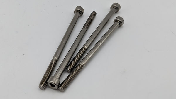
You'll need four M4 x 65mm hex bolts
2. Place the base plate under the Janky. The completely flat side should face the electronics, with the recessed holes for the bolts being on the underside of the machine.
3. On the inside of the base plate, there is some text that reads Jacks This End. Make sure this text is at the same end of the Enclosure Body as the audio and DC jacks.

Make sure the Enclosure Bottom Plate is the correct way around!
4. Thread one of the M4 x 65mm hex cap bolts into each corner. These bolts go all the way through the Enclosure Body, through the Transport Deck and into the heat set inserts in the Enclosure Lid. We went with this design because having those steel bolts through the entire height of the enclosure adds significant rigidity and makes the enclosure more robust. The downside is that it takes ages to screw them in! To get around this, we use an electric screwdriver with a hex key that fits the M4 bolts. It can also be done by hand, it'll just take a while.
5. Continue to screw the bolts in until they are flush with the surrounding plastic of the Enclosure Bottom Plate. Don't over-tighten or you risk damaging the enclosure plastic.

Tighten all four bolts until flush with the surrounding plastic, but avoid over-tightening.
7. Your Janky is now complete! Have a cup of tea. Hopefully the journey hasn't been too painful for you! Thanks for checking out the Janky and we hope you have fun making weirdo glitchy ambience noises with it.

One finished Janky!
Appendix 1.0 Debugging
A1.1 Bias Oscillator
In the case that your bias oscillator isn't functioning as you would expect, here's some useful info to help debug the cause.
First of all, it's important to make sure that
-
The erase head is connected. Without the erase head, the circuit will not function.
-
That all capacitors denoted as needing to be 100V rated, are in fact 100V rated.
-
That all capacitors marked as having to be Multilayer Ceramic Capacitors (MLCC) are and that you haven't substituted these for an alternative type.
-
That the effect is active and that the 9V supply is stable.
-
That your transistors Q2 and Q3 are not hot to the touch when the circuit is operating. Hot transistors indicates something bad is happening - most likely that the erase head is either not connected correctly or is faulty.
-
That you check all off-board wiring is solid and that you have no loose wires.
-
That you check continuity between all part junctions to make sure that there's no cold solder joints. If you follow along with the schematic then by continuity testing between all component legs/pads that should be connected in the schematic, that all components are indeed connected and there are no bad solder joints causing problems.
A1.1 Voltage Readings
Here you can see voltage test points, and the voltage readings you can expect to find during normal operation. These can be used to help trace where in the circuit a problem may be occuring.

Here are the voltage readings for each of the ten testing points marked above. All voltage readings are approximate and you should expect a little variation. The white text reading is from the voltage meter from the test point to ground, and the image shows the scope read out at that point (in DC mode).
1. 8.86V

3. 8.6V

5. 0.01V

7. 4.46V

9. 19.7V (AC).
Note that scope readings are in x10 mode
(so values are actually ten times higher than readout)

2. 8.86V

4. 4.45V

6. 0.32V

8. 4.51V

10. 4.5V

A1.2 Stuff To Try
The bias circuit is essentially a tuned LC oscillator, and as such it is very sensitive to the values of all capacitors and inductors in the circuit. The values of these components will affect the tuning of the oscillator and thus its frequency and stability.
With this in mind, electronic components are specified with certain tolerances - that the actual value of resistance, capacitance or inductance will be within a % of error of the quoted value. This means that a capacitor that claims to be 0.1uF, might in fact be 0.095uF or 0.113uF. This is entirely normal, and is due to variation in manufacturing processes - usually the tolerance % of the part is specified by the supplier. However, sometimes, parts can be "out of tolerance" - that is to say that the value falls outside of the range of what is quoted due to some defect with the part. Because of this, it's worth swapping out (or testing) parts to be sure that they aren't the cause of the problem.
-
Try a different erase head. We specify that the head should be ~800uH with a coil resistance of < 2R.
-
Try different capacitors. In the same vein as trying a different erase head, swapping out C4, C5, C6 and C7 is a good way to be sure that your issue isn't due to part tolerances. It's unlikely that your capacitors are out of tolerance, but if all else fails it is a useful check.
-
Switch out the transistors Q2 and Q3. If the circuit has been run without an erase head attached for some period of time, it's possible these have overheated and been damaged. Alternatively, they may have been heat damaged during the soldering process.
Appendix 2.0 Head Alignment
[coming::soon]
Appendix 3.0 Tuning Your Janky
[coming::soon]
Appendix 4.0 Making Your Janky Robust
[coming::soon]
Appendix 5.0 Making Head Adapters
We supply head adapters for a small number of cassette head models in the project files under the STL/Premade Head Adapters folder. However, you can choose to make your own adapters. In this section, we will show you how to do that.
A5.1 Taking Measurements
To get started with designing your own head adapter, you need to be able to measure your heads. For this, digital calipers are best. Digital calipers are a really useful tool if you plan on doing any designing of 3D printed parts, and can be found online for very reasonable money (the set we use are around £20).

A low-cost set of digital calipers is very useful!
We need three basic measurements from our specific head, X, Y and Z. Let's go through each measurement. Write each one down as you measure your cassette head.
X - The Mounting Width
This is the distance between the mounting holes in the base plate of the head.

Top-down view of the head. Measure X.
On most heads, the left-hand mounting hole is open on one side. This means that we don't need to be too accurate with our measurement, it just has to be roughly right.
Y - The Head Depth
This is the distance between the front of the pickups on the face of the head, and the center of the mounting hole.

Top-down view of the head. Measure Y.
This can be tricky to measure, due to the rounded face of the head. However, try to be as accurate as you can, as it's important in order that we get the head in the correct place. If this measurement is off, the head either won't make enough contact with the tape resulting in crackly, weak or no audio signal. Or, the head will push into the tape too much, which will cause the tape to jam.
Z - The Fork Height
This is the distance between the bottom of the base plate and the lower inside edge of the fork.

Side-on view of the head. Measure Z.
By measuring this tape fork height, we can work out how heigh our head adapter should be in order that the pickups of the head are aligned correctly with the tape.
"But, my head doesn't have a fork!" I hear you cry. In that case, you have to make a guess. This is why we typically prefer heads with forks, because they're easier to take measurements from.
Results
You should now have three measurements, X, Y and Z. Below you can see my workings for a 15RAA2 stereo cassette head.

Measurements X, Y and Z taken from an MS 15RAA2 cassette head.
By measuring this tape fork height, we can work out how heigh our head adapter should be in order that the pickups of the head are aligned correctly with the tape.
"But, my head doesn't have a fork!" I hear you cry. In that case, you have to make a guess based on the distance between the bottom of the base plate and the bottom of the pickup. This is why we typically prefer heads with forks, because they're easier to take measurements from.
The height of the Head Adapter is given by:
Height = 8mm - Z
In our case, Z was 2.6mm. So 8mm- 2.6mm is 5.4mm. So, 5.4mm is the height of my Head Adapter.
The width of the holes that connect the Head Adapter to the Head Mount is 12mm, and they should have a diameter of 2mm.
The width apart that the mounting holes for connecting the head to the Head Adapter is given by X.
The distance that the holes for connecting the head to the Head Adapter should be from the front edge of the adapter is given by the formula:
Distance To Front Edge = Y - extra
The extra is the amount we want to push the head into the tape. If we've measured everything correctly. This is different for each head, depending on the shape of the face of the head. If we increase the value of extra, the head will be pushed further into the tape (increasing tape loop tension). If we decrease the value of extra, then it will pull the head out of the tape (decreasing tape loop tension). I usually start with an extra of 1.5mm and then adjust if it isn't providing the correct contact or tape tension.
So in our case, the distance from the mounting hole center to the front edge is:
12mm - 1.5mm = 10.5mm
So, to recap. We now have five measurements:
X = 17.5mm
Y = 12mm
Z = 2.6mm
Height = 5.4mm
Distance To Front Edge = 10.5mm
A5.2 CAD Work
In order to make our Head Adapters, we need to first design them in the computer. Don't worry if you've no experience with this, we'll give you a step-by-step to follow. We'll be using the free browser-based CAD tool TinkerCAD.
We're going to be using the measurements for X, Y, Z, Height and Distance To Front Edge that we took in the previous section. You should substitute in the measurements you have taken of your cassette head.
Open TinkerCAD and select the blue +New button in the top right to create a new 3D Design.

Create a new 3D Design
The 3D workspace should appear, allowing you to drop 3D objects into the scene.
Drop a new cube into the scene by dragging and dropping the red cube object onto the work area. Once the cube is in the scene, we can select it and manipulate the various handles that appear to resize it.
Drag a cube into the scene and resize it
We set the height of the cube to the Height measurement we took, in our case that's 5.4mm.
We then set the width of the cube to 24mm and the length to 19mm. These dimensions are the same for every Head Adapter.
Now we need to add the holes for the bolts that connect the Head Adapter to the Head Mount. To do this, we need to switch view so that we can easily align the holes.
In the top left of TinkerCAD is a cube that allows you to change the orientation of the camera. Click the Top view, and it should switch the camera to a top-down view of the workspace.

Click Top!
It is also useful to switch to orthographic render - this removes 3D perspective, which makes it much easier to line up objects in the workspace by sight. Click the perspective button to switch to orthographic mode.

Switch to flat view
Your workspace view should now look like the below image.

Your view should now look like this.
Now we'll add the holes for the bolts that connect the Head Adapter to the Head Mount. Holes are created using the hole objects, which are identified by their grey appearance.

The hole objects are marked with grey lines
Add a cylindrical hole by dragging the cylinder hole object into the scene. Resize it to 2mm x 2mm. Then, place the center of the cylinder over the bottom right corner of the red box.
Add a 2mm diameter cylindrical hole object
Next, move the cylindrical hole up by 6mm, and left by 2mm.
Move the cylindrical hole to the correct position
Now we repeat the process of adding a cylindrical hole, but this time from the top right corner. The result should be that we have two 2mm holes, 12mm apart and 2mm into the adapter from the right hand edge.
Repeat the process to add the second mounting hole
Your adapter should now look like the image below.

Your head adapter should have both mounting holes now.
Once both mounting holes are in place, we need to add the geometry for our head to connect to the adapter.
Add another 2mm diameter cylinder, this time position it over the top left corner of the adapter. Then, move it inward by Distance To Front Edge. In our case, this was 10.5mm.
Begin adding the mounting holes for the head itself
So the hole is hopefully now the correct distance from the front edge of the adapter. Now we want to move this hole down so that it is embedded into the plastic. The distance we need to move it down relates to X, which was the distance apart the mounting holes on the head are.
The adapter is 24mm wide, so we can work out the position of the hole like this:
W = ( 24mm - X ) / 2
In our case, X was measured as being 17.5mm. So, for us, W is:
W = ( 24mm - 17.5mm ) / 2 = 3.25mm
So I move the hole down by 3.25mm.
Move the mounting hole down the correct amount for your heads X measurement
Your adapter should now look similar to the image below. Remember that the exact positioning of your head mounting hole will differ, depending on the measurements you have taken.

Head adapter with one of the head mounting holes in place
Next we repeat this process but from the bottom left corner to position the opposite mounting hole.
Add the second head mounting hole
Now select the red box and all of the hole cylinders. Then, in the upper right hand tool bar, select the Group option.
Group the objects together in order to apply the holes
The Head Adapter should now look similar to the image below.

Both head mounting holes in place
At this point, the Head Adapter could be exported and printed if you so wish. We have the mounting holes and dimensions correct enough that it should work. However, to improve performance by allowing you to adjust the heads position and angle, we can also add space for a spring under the head. Add a 5mm diameter cylindrical hole over the top of the bottom most head mounting hole, as in the video below.
Add another cylinder where we will form the spring position
Click the bottom left corner of the view selection cube to switch to an angled view of the workspace.

Click the corner!
The workspace should resemble the below image. The hole we've added for the spring should be jutting out of the top of the adapter.

The head adapter, with spring hole in place
We want this hole to only cut a small way into the top of the adapter, 1.15mm to be precise. So adjust the height of the cylindrical hole so that it only cuts 1.15mm away from the top surface. In the video below, I do this by shrinking the height of the cylinder until it's flush with the top surface, and then increasing it's height by adding 1.15mm. Then, I select everything and hit the Group button again to apply the cylindrical cut.
Adjust the height of the spring hole until it cuts away just the right amount of plastic from the top surface of the adapter.
The Head Adapter is now finished, and should look similar to the image below.

The finished Head Adapter, ready to export and print!
Select Export on the top right panel.

Click Export!
In the Export dialog box that appears, select .STL to download your design as a 3D printable STL file. From there, you can use your slicer of choice to convert this file into gcode for your printer.

Click .STL to download your Head Adapter STL file
Once your Head Adapter is installed into the machine, you may find that your head is either not pressed into the tape enough, or is pressed in too far. Either way, it will result in the wrong tension in the loop that can cause a low or no signal, or can cause the loop to jam. If that is the case, simply adjust the extra that we added to the Distance To The Front Edge in Appendix A5.1 in order to move the head into or out of the loop.
Appendix 6.0 Making XH Connectors
In this section, we're going to show you how to make a JST XH connector.
You will need a JST XH compatible crimping tool. Official tools are hyper-mega expensive, however knock-off tools are available for reasonable money. The tool we use can be had on Amazon for £36.
I

A cheap-o JST XH connector kit, complete with crimp tool and headers.
A6.1 How To Crimp a JST XH Header
XH headers come in three parts.

Female header

Male housing

Crimp contact
For this project, you will need female headers and male housings in both 2 pin and 3 pin sizes. Sometimes the crimp contacts are supplied on a strip (as seen in the image above), from which you break your crimp contact off when you want to use it. And sometimes they are supplied loose.
The crimp contacts are attached to the bare ends of wire using a crimping tool, and then slotted into the male housing so that the male housing can be push-fit onto the female header to make a solid connection.
Here's how you do that.
1. Take the length of wire you wish to crimp and strip around 2mm to 3mm of insulation from the end. The amount of insulation removed is a fair bit less than what you ordinarily might do for a wire you were going to hand solder.

Strip 2 or 3mm of insulation from the end of the wire
2. If using stranded wire, twist the wire together to make it neat. We find it's best not to tin the wire, but instead leave it free of solder. This is because the solder makes the wire more brittle and prone to breaking, as well as the heat from the iron weakening the insulation that the crimp connector will bite down into.
3. Place your crimp connector into the appropriate slot on the crimp tool. Usually, crimping tools provide different slots for wires of different gauges - in practice it often takes some experimenting with the different slots to figure out which one works best for your particular size and type of wire. Ensure you place the crimp in the correct orientation. The 'wings' at the back of the crimp connector face upward. You will notice that the inside of the slot on the crimp tool is ridged. The wings should be placed into the side of the tool which is widest, so that the wings are held in place against that ridge. The front of the crimp connector features a tiny barb, which when the crimp connector is placed into the male housing holds the connector in place. Be sure that this barb is outside of the crimp tool and so won't be crushed flat. Close the jaws of the tool one or two clicks, just enough to hold the crimp connector in place.

One side of the jaws has a ridge in each slot

Place the wings of the connector into the slot so that they are up against the ridge, facing upward as shown here.

Make sure you don't crush the barb in the jaws.
4. Feed the bare end of the wire through the side with the wings of the connector, so that the end of the insulation is lined up with the front of the wings. We don't want too much insulation in else it will result in a poor electrical contact. Likewise we don't want too little insulation in, or the wings will not bite down on it enough and the wire may come loose from the crimp.

Feed the wire through the wings, just enough for the wings to cover the insulation.
5. Close the crimp tool all the way down, so that it crushes the crimp connector onto the wire. Once the crimp tool has been fully closed it should pop open again, allowing you to release the crimp connector. The connector should now be nicely crimped onto the wire.

Close the jaws all the way. Once the jaws are completely closed, the ratchet should release, allowing the jaws to open again.

The crimped wire in all its glory!

The barb, still intact.
6. Slide the crimp connector with it's newly attached wire into a slot on the male housing. Ensure the barb is facing the side of the housing with the opening at the end - this is the hole that the barb hooks onto to prevent it slipping out. If you put the connector in the wrong way around it will not lock in place.

Push the crimp into the housing. The barb should click into the hole in the face of the housing.
7. The male housing press fits into the female header and clicks in place. The pins of the female headers solder into the appropriate pads on the PCBs. Make sure you solder the headers the correct way around so that the wires match up with the correct pads. Once the header is the correct way around, and the wires are slotted into the correct slots on the header, the connector will only go together one way around. This prevents you accidentally connecting the motor or power connections the wrong way around when servicing the machine.
Some further tips;
-
Usually, crimp tools have an adjustable force setting that can increase or reduce the force with which they crush the crimp connector onto the wire. When dealing with very thin wires, as is the case in a small electronics build such as this, it's useful to set the crimp tool to one of the lowest force settings. If the force is set too high it will likely either damage the wire, creating a poor contact, or it will cut clean through the wire. To adjust the force look for a small locking washer on the side of the tool. They can be fiddly to adjust so take your time and make sure to look at the instructions supplied with your tool.
-
Avoid crimping very thin wires. Instead, replace or extend thin wires with a thicker gauge so that you get a stronger, more reliable crimp.
-
Crimping is somewhat of an art. It can be frustrating and fiddley when you're not used to doing it. Take time to practice a few crimps on scraps of wire to ensure you can get a good contact before letting loose on your build.
-
Don't strip too much insulation from the end of the wire you're trying to crimp - if the exposed wire is too long it will interfere with the hole through which the pin of the female header connects.
-
Try not to pretend that the crimping tool is a dinosaur.
Appendix 7.0 Legal Mumbo-Jumbo
The Indifferent Engine Janky Tape Echo is licensed to the public as open source under GNU General Public License 3.0. Everything is copyright ©2023 Indifferent Engine Ltd. Indifferent Engine and the Indifferent Engine glitch logo are trademarks of Indifferent Engine Ltd.
Credits
The Janky Tape Echo was developed over two years by

Adam Paul
CAD, Electronics, Software

Tom Wilson
Electronics, Tuning, Testing
The band would like to thank the following people:
All the people at the diystompboxes forum for help, inspiration and making such a cool and genuine community of pedal hackers. We'd especially like to thank Jarmo "jatalahd" L. for answering all of Adam's stupid questions. Our friends in Praetorian, The Grey and Estranger for the good gigs and the inspiring music. Hackaday, it's a daily read for us to get inspired. Bob Mardon and all the people at Club 85 for running the best venue around and putting up with our TV rig. Steve Pedulla for being a guinea pig and general, all-around cool guy. Holy Island Audio for the Tides. Orange amps because we love our Rockerverbs.